Projection display with polarization beam splitter

Active Publication Date: 2004-12-30
SAMSUNG ELECTRONICS CO LTD
View PDF8 Cites 6 Cited by
  • Summary
  • Abstract
  • Description
  • Claims
  • Application Information

AI Technical Summary

Problems solved by technology

A 3-panel projection system provides better light efficiency than a single-panel projection system but is more complicated and expensive than the single-panel projection system.
Hence, the conventional optical system is bulky, and the manufacturing and assembly thereof is complicated, thus decreasing the yield.
Thus, the projection system adopting three motors is manufactured at a greater cost than a color wheel type projection system which utilizes a single motor.
However, controlling the synchronization is not easy.
Due to the circular motion of the scrolling prisms 114, 135, and 142, the color scrolling speed by the three scrolling prisms is irregular, consequently deteriorating the quality of the resultant image.
Since the dielectric-coated MacNeille type PBS does not properly split a beam with a wide incidence angle according to polarization direction, contrast is degraded.

Method used


Image

  • Projection display with polarization beam splitter
  • Projection display with polarization beam splitter
  • Projection display with polarization beam splitter

Examples


Embodiment Construction

[0042] The present invention will now be described more fully with reference to the accompanying drawings, in which illustrative, non-limiting embodiments of the invention are shown. In the drawings, like reference numbers refer to like elements throughout, and the sizes of elements may be exaggerated for clarity.

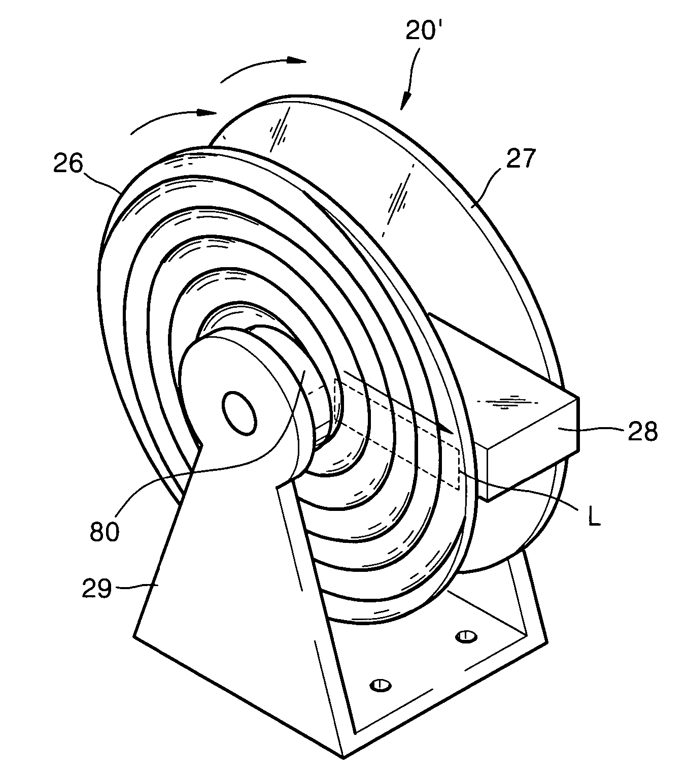
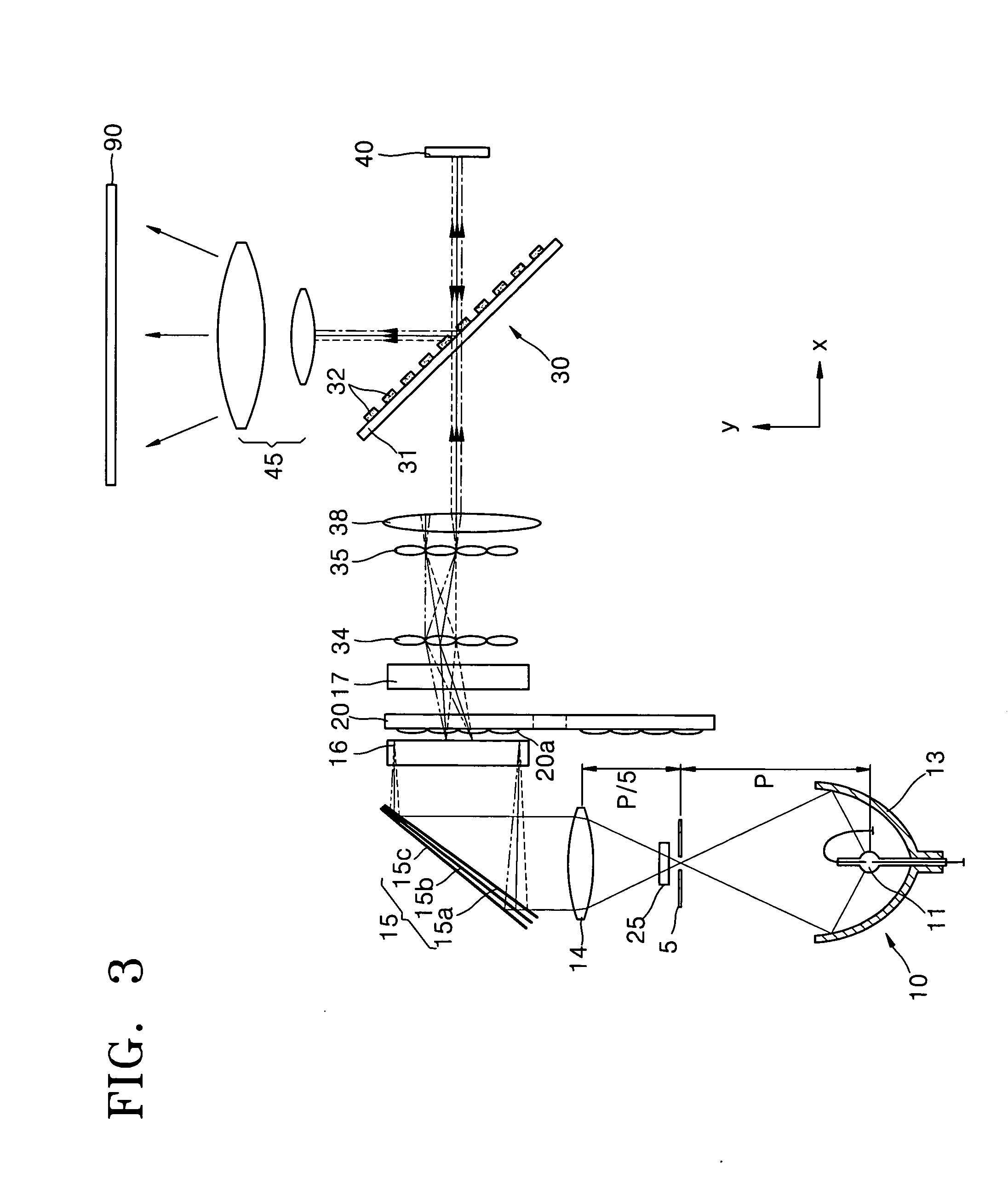
[0043] FIG. 3 is a schematic diagram of a projection system according to a first embodiment of the present invention. Referring to FIG. 3, the projection system according to the first embodiment of the present invention includes a light source 10, a color separator 15, a scrolling unit 20, a light valve 40, a wire grid polarization beam splitter 30, and a projection lens unit 45. The color separator 15 separates light emitted from the light source 10 into color beams, namely, R, G, and B beams. The scrolling unit 20 scrolls R, G, and B beams, into which the beam emitted from the light source 10 has been separated by the color separator 15. The light valve 40 processes the b...


PUM


Abstract

A projection system including a light source, a color separator, a scrolling unit, a light valve, a wire grid polarization beam splitter, and a projection lens unit is provided. The color separator separates an incident beam according to color. The scrolling unit scrolls the color beams. The light valve processes an incident beam according to an image signal and forms a color picture. The wire grid polarization beam splitter is disposed between the scrolling unit and the light valve and transmits or reflects an incident beam according to a polarization of the incident beam. The projection lens unit magnifies the color picture formed by the light valve and reflected by the wire grid beam splitter and projects the magnified color picture onto a screen.

Description

[0001] This application claims the priority of Korean Patent Application No. 2003-23975, filed on Apr. 16, 2003, in the Korean Intellectual Property Office, and the benefit of U.S. Patent Provisional Application No. 60 / 457,568, filed on Mar. 27, 2003, in the U.S. Patent Trademark Office, the disclosures of which are incorporated herein in their entireties by reference.[0002] 1. Field of the Invention[0003] An apparatus consistent with the present invention relates to a projection system and, more particularly, to a projection system which can improve contrast using a wire grid polarization beam splitter.[0004] 2. Description of the Related Art[0005] In a conventional projection system, a light valve, such as a liquid crystal display (LCD) or a Digital Micro-mirror Device (DMD), controls the on / off operation of light emitted from a light source on a pixel-by-pixel basis and forms a picture, and a magnifying projection optical system enlarges the picture to be displayed on a large scr...

Claims


Application Information

Patent Timeline
IPC IPC(8): G03B21/20G03B21/14H04N9/31
CPCH04N9/3117H04N9/3197G03B21/2073G03B21/208G03B21/14
Inventor KIM, SUNG-HACHO, KUN-HOKIM, DAE-SIKLEE, HEE-JOONG
Owner SAMSUNG ELECTRONICS CO LTD
Why Eureka
Try Eureka