Air compressor and control method therefor

a technology of air compressor and control method, which is applied in the direction of pump control, positive displacement liquid engine, pump pump, etc., can solve the problems of insufficient power supply environment, physical discomfort, and inability to avoid and achieve the effect of improving the power supply environment and avoiding the generation of considerable nois

Inactive Publication Date: 2004-12-30
HITACHI KOKI CO LTD
View PDF5 Cites 93 Cited by
  • Summary
  • Abstract
  • Description
  • Claims
  • Application Information

AI Technical Summary

Problems solved by technology

Since an air compressor includes a mechanism for converting the rotation of a motor into the reciprocal movement of a piston in a cylinder, the generation of considerable noise can not be avoided.
Further, since a nailer that uses air compressed by an air compressor also generates noise while in operation, there is considerable noise pollution, and physical discomfort, in an area surrounding a construction site whereat both air compressors and pneumatic nailers are being employed.
Locations whereat air compressors are employed are not always satisfactory power supply environments; on the contrary, air compressors are frequency used in environments wherein sufficiently high voltages can not be obtained because long cords, stretched from other locations, are employed to supply power, or in environments wherein voltages fluctuate because multiple tools are in u...

Method used


Image

  • Air compressor and control method therefor
  • Air compressor and control method therefor
  • Air compressor and control method therefor

Examples


Embodiment Construction

[0053] The preferred embodiment of the present invention will now be described in detail.

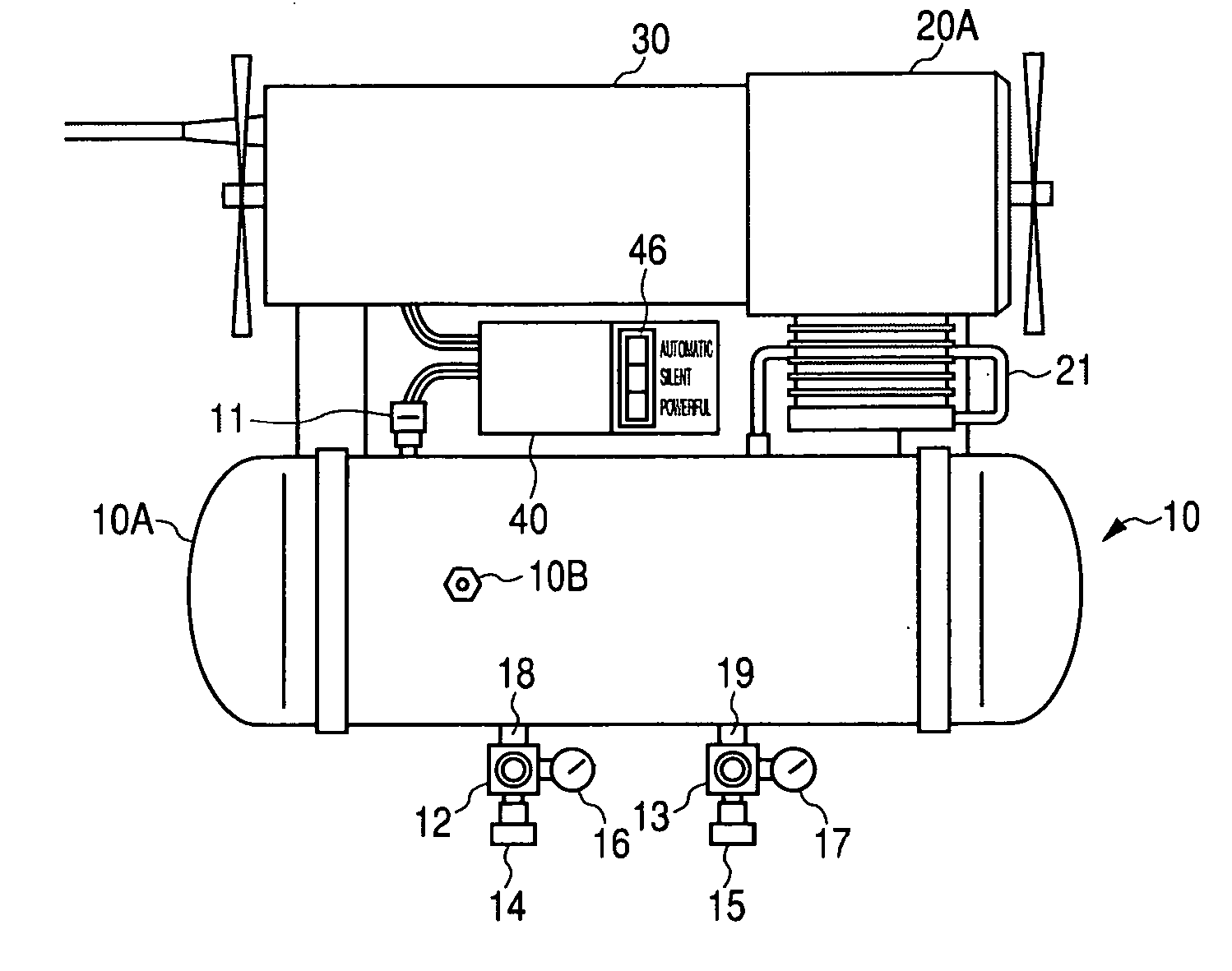
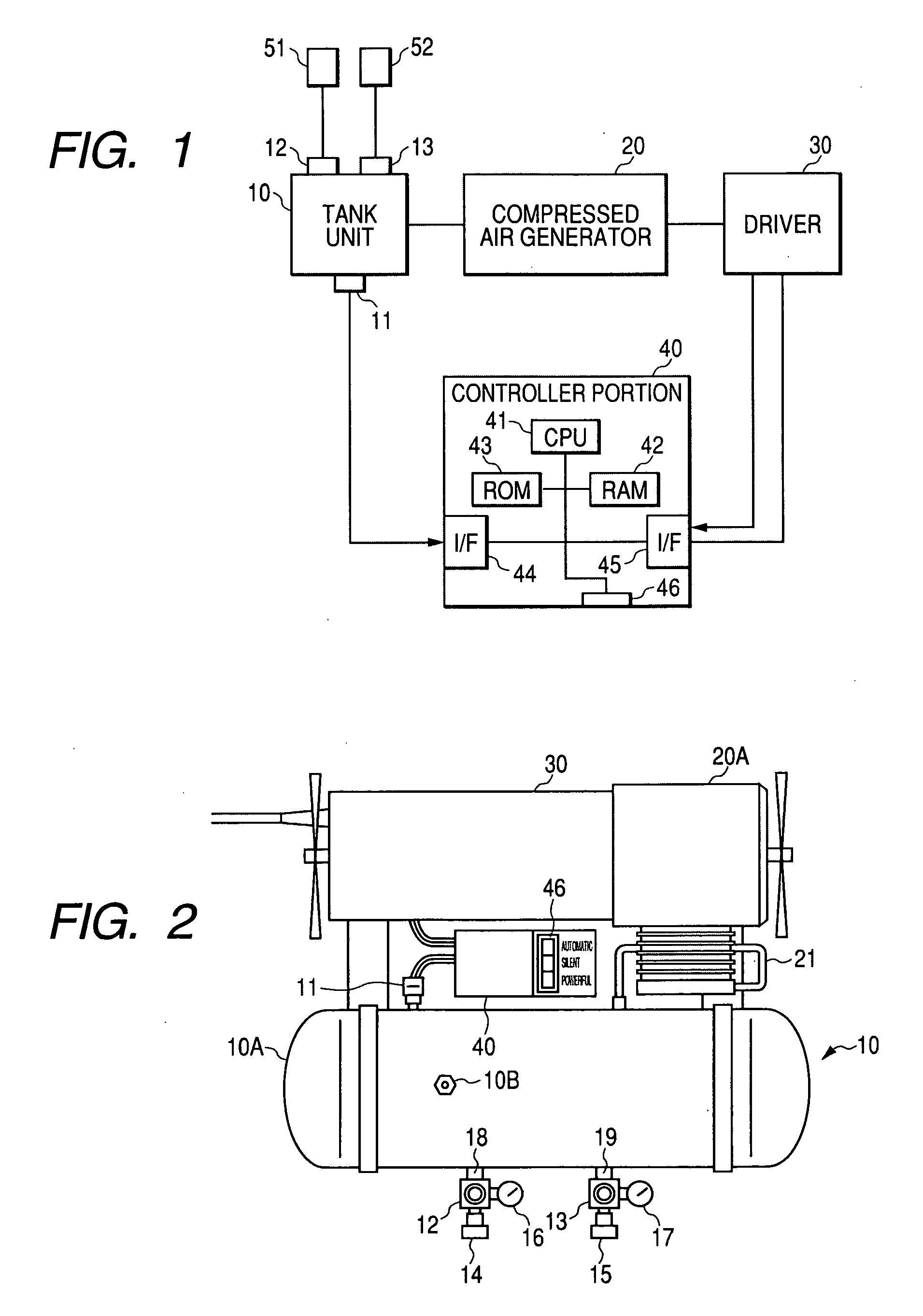
[0054] As is shown in a conceptual diagram in FIG. 1, an air compressor according to the invention comprises: a tank unit 10, for storing compressed air; a compressed air generator 20, for generating compressed air; a drive portion 30, for driving the compressed air generator 20; and a controller portion 40, for controlling the drive portion 30.

[0055] (1) Tank Unit 10

[0056] As is shown in FIG. 2, the tank unit 10 includes an pressure tank 10A, for storing compressed air, to which high-pressure, 20 to 30 kg / cm.sup.2 compressed air is supplied through a pipe 21 connected to the discharge port of a compressor 20A.

[0057] Generally, a plurality of compressed output ports 18 and 19 are provided for the pressure tank 10A, and in this embodiment, the output port 18 is used to feed low-pressure compressed air and the output port 19 is used to feed high-pressure compressed air. The present invention, howe...


PUM


Abstract

For a motor that drives a compressed air generator, three operating modes which includes a powerful mode for rotating a motor in a high speed range, a silent mode for rotating the motor in a low speed range, and an automatic mode for automatically changing the rotation speed of the motor from the low speed to the high speed in accordance with a setup condition are prepared. A user can designate a desired operating mode by using an operating mode selection switch.

Description

[0001] 1. Field of the Invention[0002] The present invention relates to an air compressor for compressing air and is applied for the operation of a pneumatic tool, such as a nailer, and a control method therefor.[0003] 2. Description of the Related Art[0004] An air compressor applied for the operation of pneumatic tools is generally designed so that as a motor rotates a crankshaft in the main body of the air compressor, a piston served by the crankshaft reciprocates within a cylinder and compresses air supplied via an intake valve. Thereafter, the compressed air is discharged from the main body of the air compressor, through an air release valve and a pipe, to an pressure tank for storage. The compressed air stored in this tank can then be applied for the operation of pneumatic tools used for nailing.[0005] Since air compressors are frequently employed outdoors, such as at construction sites or in locations whereat houses are constructed close together, the present inventors, based ...

Claims


Application Information

Patent Timeline
IPC IPC(8): F04B49/06
CPCF04B49/06
Inventor IIMURA, YOSHIOORIKASA, HIROAKISUNAOSHI, MITSUHIROSEGAWA, KAZUHIRO
Owner HITACHI KOKI CO LTD
Why Eureka
Try Eureka