Railway car drive system

Active Publication Date: 2005-01-06
HITACHI LTD
View PDF5 Cites 8 Cited by
  • Summary
  • Abstract
  • Description
  • Claims
  • Application Information

AI Technical Summary

Benefits of technology

[0010] The object of the present invention is to solve the above-mentioned problems of the prior art. That is, the present invention provides a railway car drive system for accelerating and decelerating a train by operating a driving motor driven via a power converter using power generated through the power generation means as its power source, the system being capable of optimizing the power gene

Problems solved by technology

However, if the storage capacity of the power storage means is not large enough with respect to the power required to run the train, which may be the case if the power capacity of the power storage means is minimized so as to reduce the size and weight of the devices mounted on the cars that constitute the train, it may

Method used


Image

  • Railway car drive system
  • Railway car drive system
  • Railway car drive system

Examples


Embodiment Construction

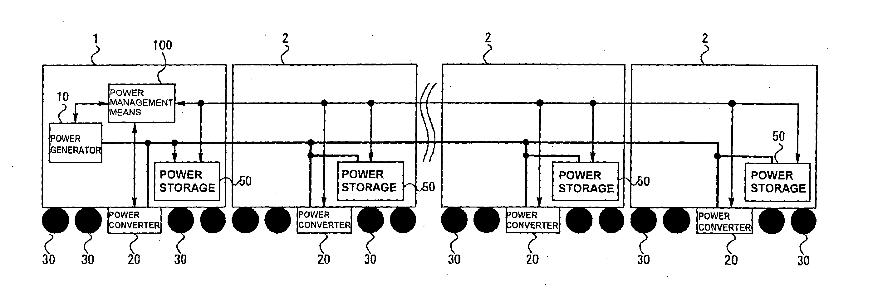
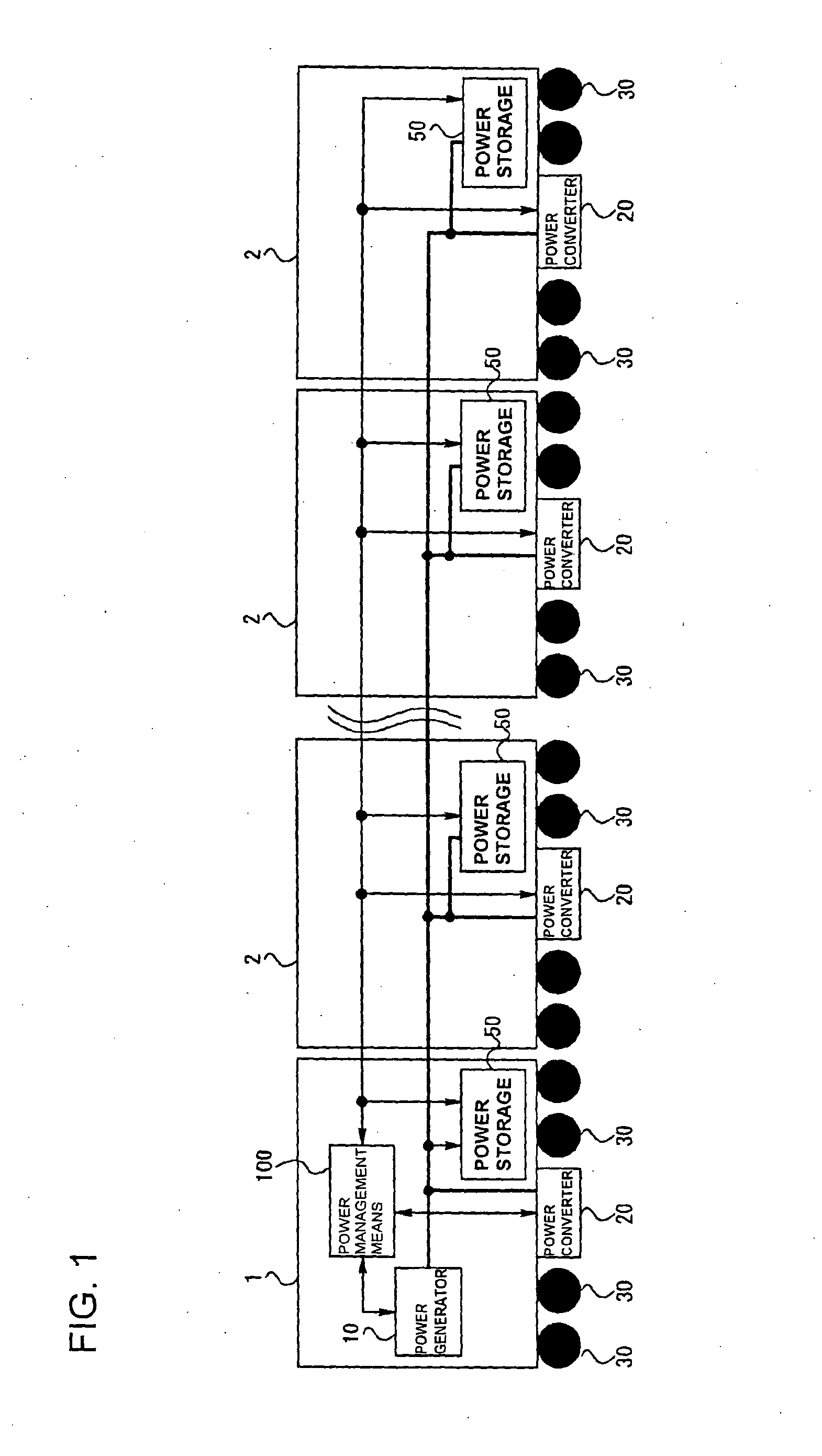
[0018] Now, one example of a preferred embodiment of the railway car drive system according to the present invention will be explained with reference to FIG. 1.

[0019] In FIG. 1, the railway car drive system according to the present invention comprises a first railway car 1 mounting a power generation means 10 and a power converting means 20 for controlling a driving motor not shown for driving plural driving wheels 30; a plurality of second railway cars 2, 2, 2 each mounting a power converting means 20 for controlling the driving motor not shown that drive the driving wheels 30 and a power storage means 50; a power transmission means 40 that connect the power generation means 10 with each power converting means 20 and each power storage means 50 for supplying the power generated at the power generation means 10 to each power converting means 20; and a power management means 100 mounted on the first railway car 1 for managing the generated power of the power generation means 10 disp...


PUM


Abstract

A railway car drive system comprising a first railway car 1 mounting a power generation means 10, a power converter 20, a driving motor and a power storage means 50; a second railway car 2 mounting a power converter 20, a driving motor and a power storage means 50; and a power transmission means 40 connecting each said means; wherein said system further comprises a power management means 100 for controlling the generated power of the power generation means 10 and the power storage quantity of the power storage means 50, the power storage means 50 storing the power generated by the power generation means 10 and a regenerative power, the driving motor being driven via the power converter 20 using as power source the power generation means 10 and the power storage means 50 to thereby run the train.

Description

FIELD OF THE INVENTION [0001] The present invention relates to a railway car drive system for accelerating and decelerating a train by driving a motor via a power converter using power generated by a power generation means as its power source, and further relates to a railway car drive system that enables to optimize the power generation capacity of the power generation means, to reduce the size and weight of the devices mounted on the railway car, and to improve the power efficiency and reliability of the drive system. DESCRIPTION OF THE RELATED ART [0002]FIG. 4 shows one example of a system configuration for accelerating and decelerating a train (railway car drive system) using power generated by a power generation means as its power source. The railway car drive system shown in FIG. 4 comprises a first railway car 1 mounting a power generation means 10 for generating the power for driving the train, and plural second railway cars 2 each mounting a power converter 20 that utilizes...

Claims


Application Information

Patent Timeline
IPC IPC(8): B60L50/15B61C3/02B61C7/04B61C9/24
CPCB60L11/12B61C7/04B60L2200/26Y02T30/16Y02T10/7077B60L50/15Y02T30/00Y02T10/7072
Inventor INARIDA, SATORU
Owner HITACHI LTD
Why Eureka
Try Eureka