Film forming device

a technology of film forming and forming tubes, which is applied in the direction of coatings, chemical vapor deposition coatings, electric discharge tubes, etc., can solve the problem of taking a long time to heat the showerhead, and achieve the effect of high temperature stability and easy maintenance of the showerhead

Inactive Publication Date: 2005-01-06
TOKYO ELECTRON LTD
View PDF21 Cites 80 Cited by
  • Summary
  • Abstract
  • Description
  • Claims
  • Application Information

AI Technical Summary

Benefits of technology

[0009] This invention is intended to solve the above problems. The object of this invention is to provide a film-forming apparatus that can lead a showerhead to a predetermined temperature within a short time and wherein temperature stability of the showerhead is high, and to provide a film-forming apparatus wherein maintenance of the showerhead can be easily conducted.

Problems solved by technology

Thus, the showerhead has to be heated over 425° C., in particular over 500° C. In a conventional art, it takes a long time to heat the showerhead, and it is uncertain whether the showerhead is at a desired temperature, so that such a stable film may not be generated.

Method used


Image

  • Film forming device
  • Film forming device
  • Film forming device

Examples


Embodiment Construction

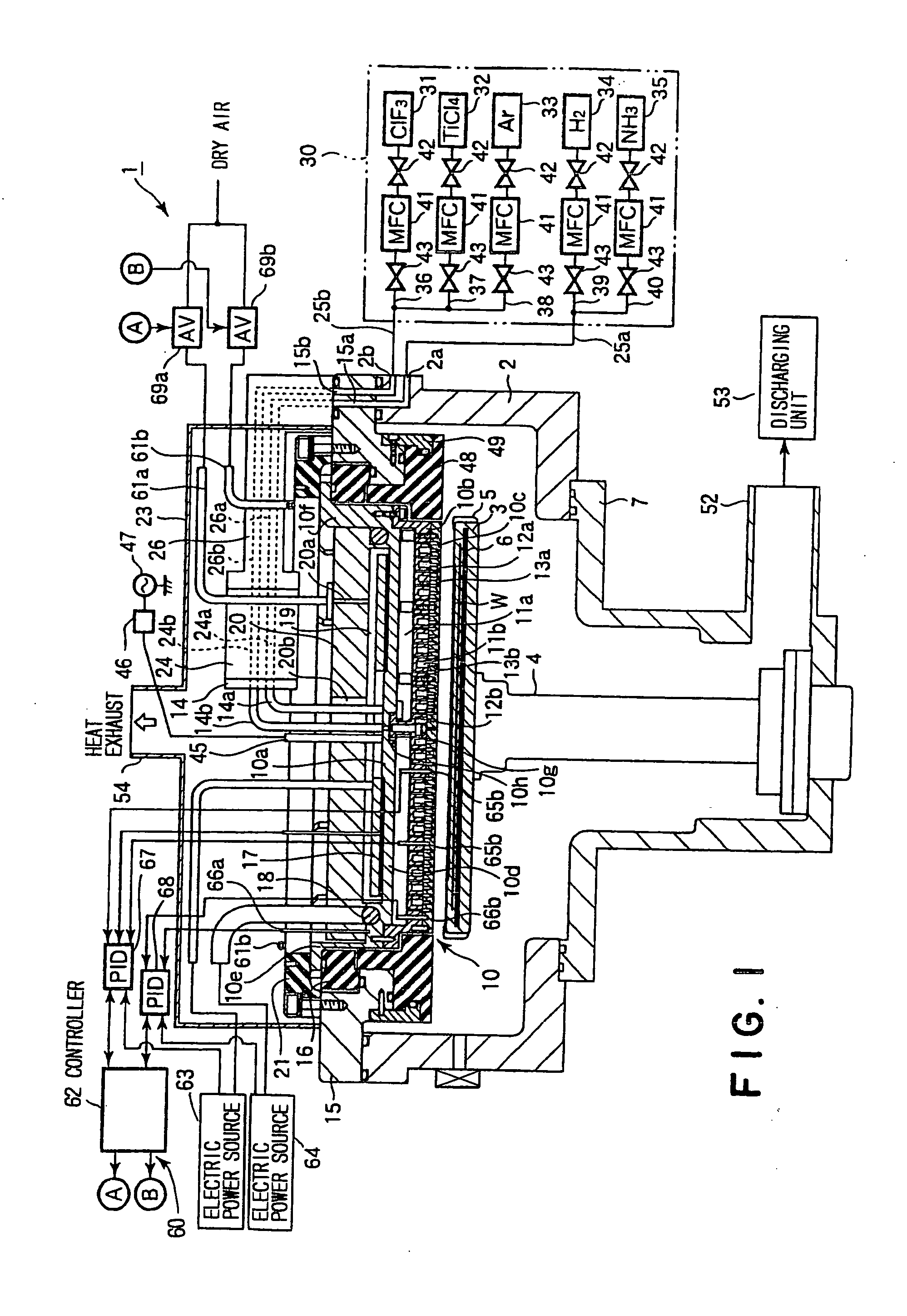
[0053] Hereinafter, a CVD film-forming apparatus for forming a Ti thin film according to an embodiment of the present invention is explained concretely.

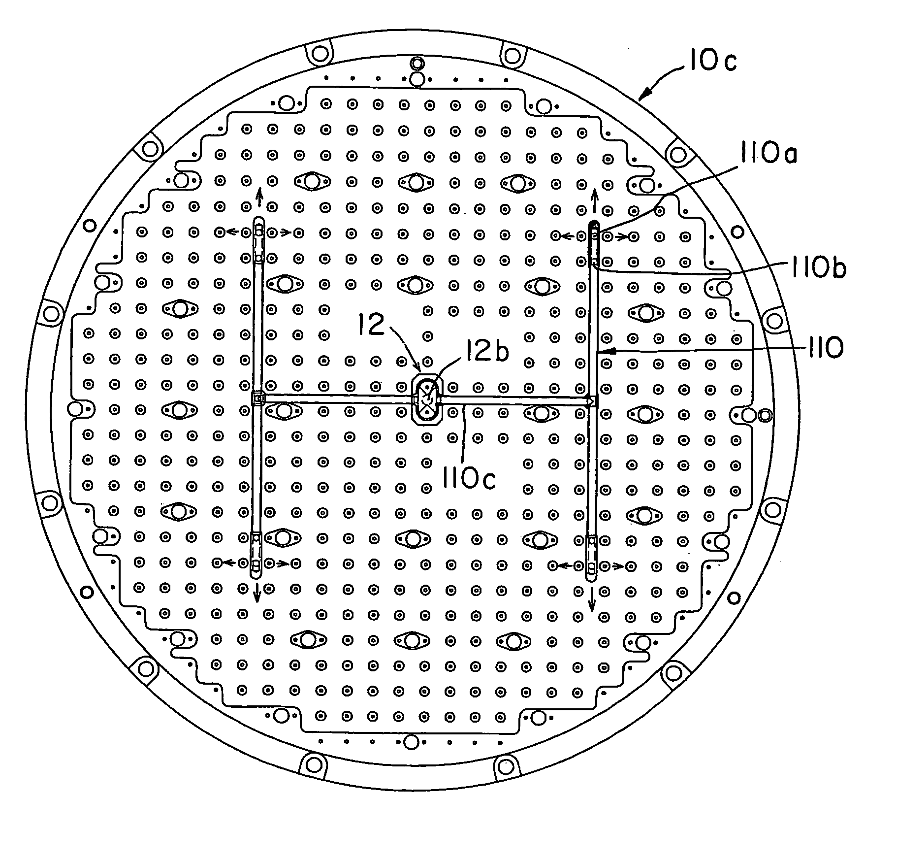
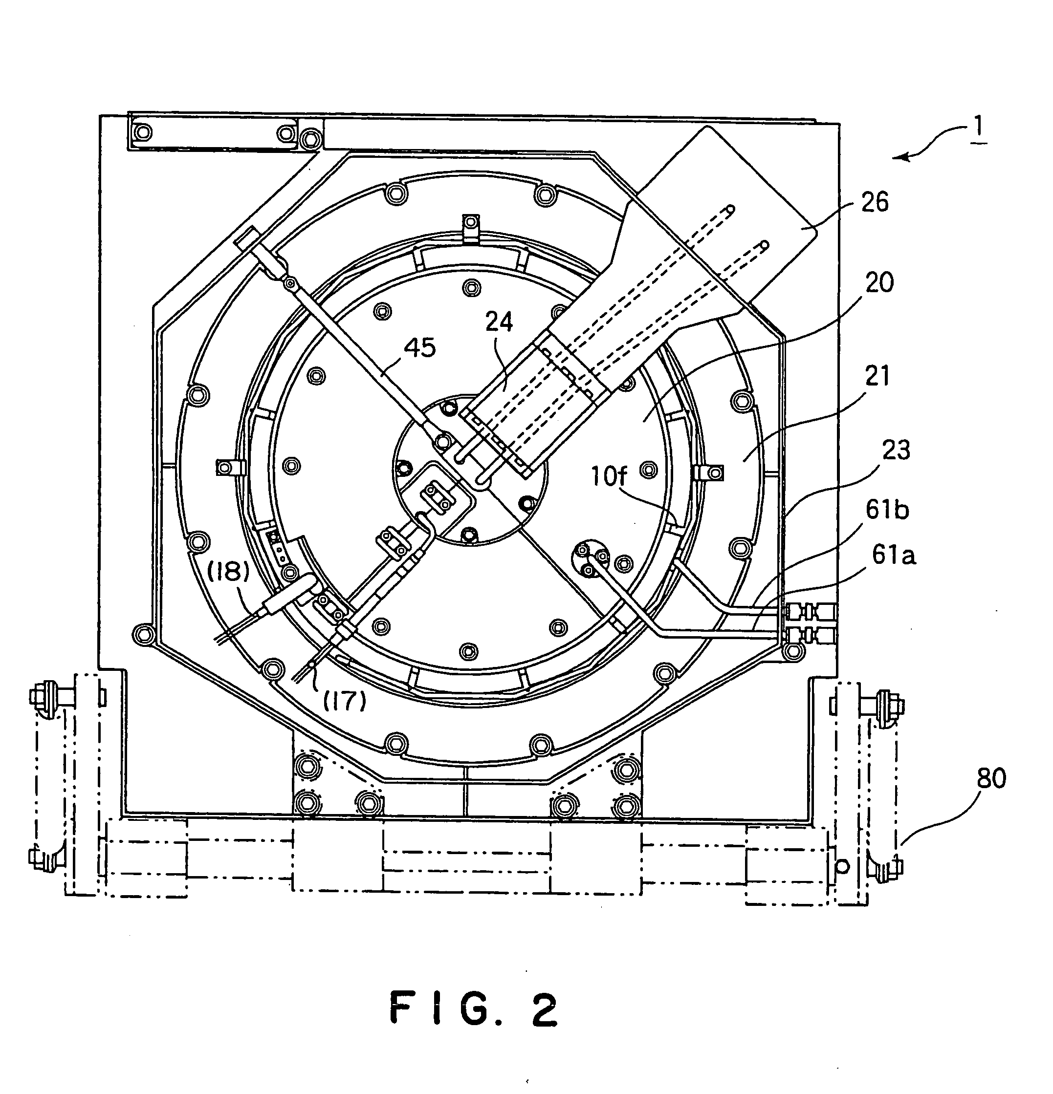
[0054]FIG. 1 is a sectional view showing the CVD film-forming apparatus for forming a Ti thin film according to the embodiment of the present invention. FIG. 2 is a plan view showing an upper portion of a showerhead of the CVD film-forming apparatus of FIG. 1. The film-forming apparatus 1 has a sealed chamber 2 of a substantially cylindrical shape or a box-like shape. A pedestal 3, on which a semiconductor wafer W as an object to be processed is placed horizontally, is provided in the chamber 2. A pedestal supporting member 7 that protrudes downward is attached at a central bottom of the chamber 2 via a sealing ring. A cylindrical supporting member 4 joined to a bottom surface of the pedestal 3 is fixed to the pedestal supporting member 7. The chamber 2 and the pedestal supporting member 7 have heating mechanisms not shown. An elect...


PUM

PropertyMeasurementUnit
temperatureaaaaaaaaaa

Abstract

A film-forming apparatus of the invention is a film-forming apparatus that includes: a processing container that defines a chamber, a pedestal arranged in the chamber, on which a substrate to be processed can be placed, a showerhead provided opposite to the pedestal, which has a large number of gas-discharging holes, a gas-supplying mechanism that supplies a process gas into the chamber through the showerhead, and a showerhead-temperature controlling unit that controls a temperature of the showerhead.

Description

FIELD OF THE INVENTION [0001] This invention relates to a film-forming apparatus that forms a predetermined thin film onto a substrate to be processed by means of chemical vapor deposition process (CVD). BACKGROUND ART [0002] In a semiconductor-device manufacturing process, in order to fill holes between electric wirings formed on a semiconductor wafer as an object to be processed, or in order to provide barrier layers, a metal such as Ti, Al or Cu and / or a metal compound such as WSi, TiN or TiSi is deposited to form a thin film. [0003] Conventionally, such thin film of the metal or metal compound is deposited by means of physical vapor deposition process (PVD). However, recently, it is requested to make devices micro and highly integrated, so that design-rule is especially severe. Thus, it is difficult to obtain sufficient properties by PVD, which is inferior in filling performance. Then, such thin film starts to be deposited by CVD, which we can expect forms a film of better quali...

Claims


Application Information

Patent Timeline
Patent Type & Authority Applications(United States)
IPC IPC(8): C23C16/44C23C16/455H01J37/32H01L21/285
CPCC23C16/45565C23C16/4557H01L21/28556H01J37/3244C23C16/45572
Inventor KASAI, SHIGERUKAKEGAWA, TAKASHI
Owner TOKYO ELECTRON LTD
Why Eureka
Try Eureka