Fuel supply apparatus and vapor separator in outboard engine

a technology of vapor separator and fuel supply equipment, which is applied in the direction of liquid fuel feeders, machines/engines, and feed systems, etc., can solve the problems of deteriorating engine performance large amount of vapor generated at high temperature conditions, and atmospheric pollution, so as to prevent the generation of vapor in the vapor separator, reduce the heat generation of the fuel pump, and prevent the effect of fuel temperature ris

Inactive Publication Date: 2005-01-06
AISAN IND CO LTD
View PDF10 Cites 9 Cited by
  • Summary
  • Abstract
  • Description
  • Claims
  • Application Information

AI Technical Summary

Benefits of technology

[0019] In this vapor separator, the fuel pump is controlled by the pump control means based on the fuel pressure detected by the fuel pressure sensor so that the pressure of fuel (on a high pressure side) discharged from the fuel pump reaches a target fuel pressure. Accordingly, regardless of the fuel pressure on a low pressure side, the fuel pressure on the high pressure side can be regulated continuously at a constant level. As a result, the air / fuel (A / F) ratio can be more stabilized.
[0020] The fuel pump is driven by a required amount by the pump control means. This makes it possible to reduce heat generation in the fuel pump, preventing a rise in temperature of the fuel in the vapor separator. Therefore, the generation of vapor in the vapor separator can be prevented. Because the fuel pump is driven by the required amount by the pump control means, furthermore, a reduction in power consumption of the fuel pump can be achieved.

Problems solved by technology

This is because the vapor generated in the vapor separator 100 is combustible, which may cause a fire if released into the atmosphere and cause atmospheric pollution.
However, the vapor separator of the fuel supply apparatus in the outboard engine, including one disclosed in Japanese patent unexamined publication No. 2001-140720, has a disadvantage that a large amount of vapor is generated at high temperature conditions due to heat, vibration, agitation caused by supplied fuel and return fuel, and decompression and boiling of the return fuel, and the vapor would be mixed in the air layer.
This would deteriorate engine performances at the high temperature conditions.

Method used


Image

  • Fuel supply apparatus and vapor separator in outboard engine
  • Fuel supply apparatus and vapor separator in outboard engine
  • Fuel supply apparatus and vapor separator in outboard engine

Examples


Embodiment Construction

[0042] A detailed description of a preferred embodiment of an engine system of an outboard engine including a fuel supply apparatus and a vapor separator embodying the present invention, will now be given referring to the accompanying drawings.

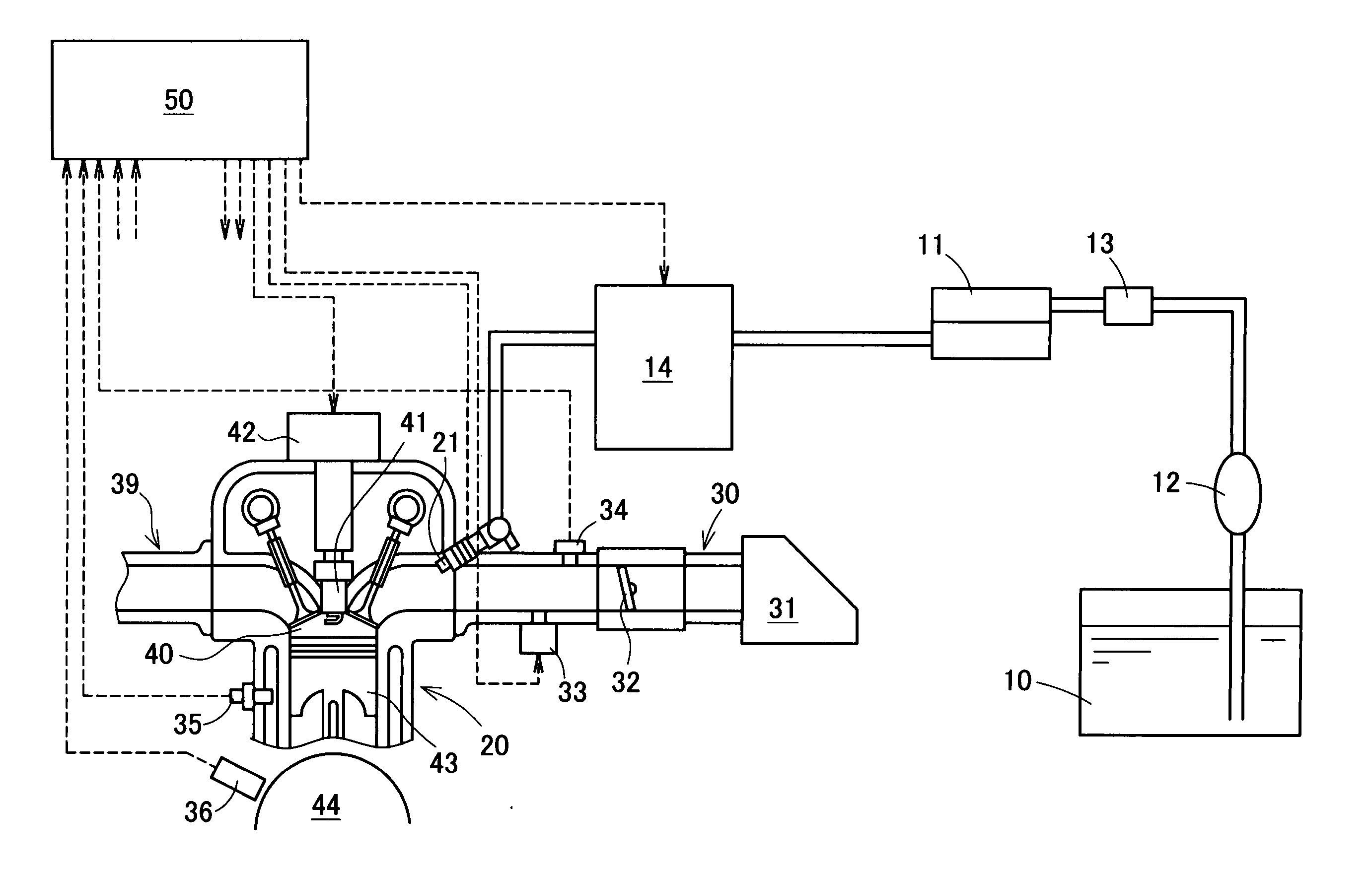
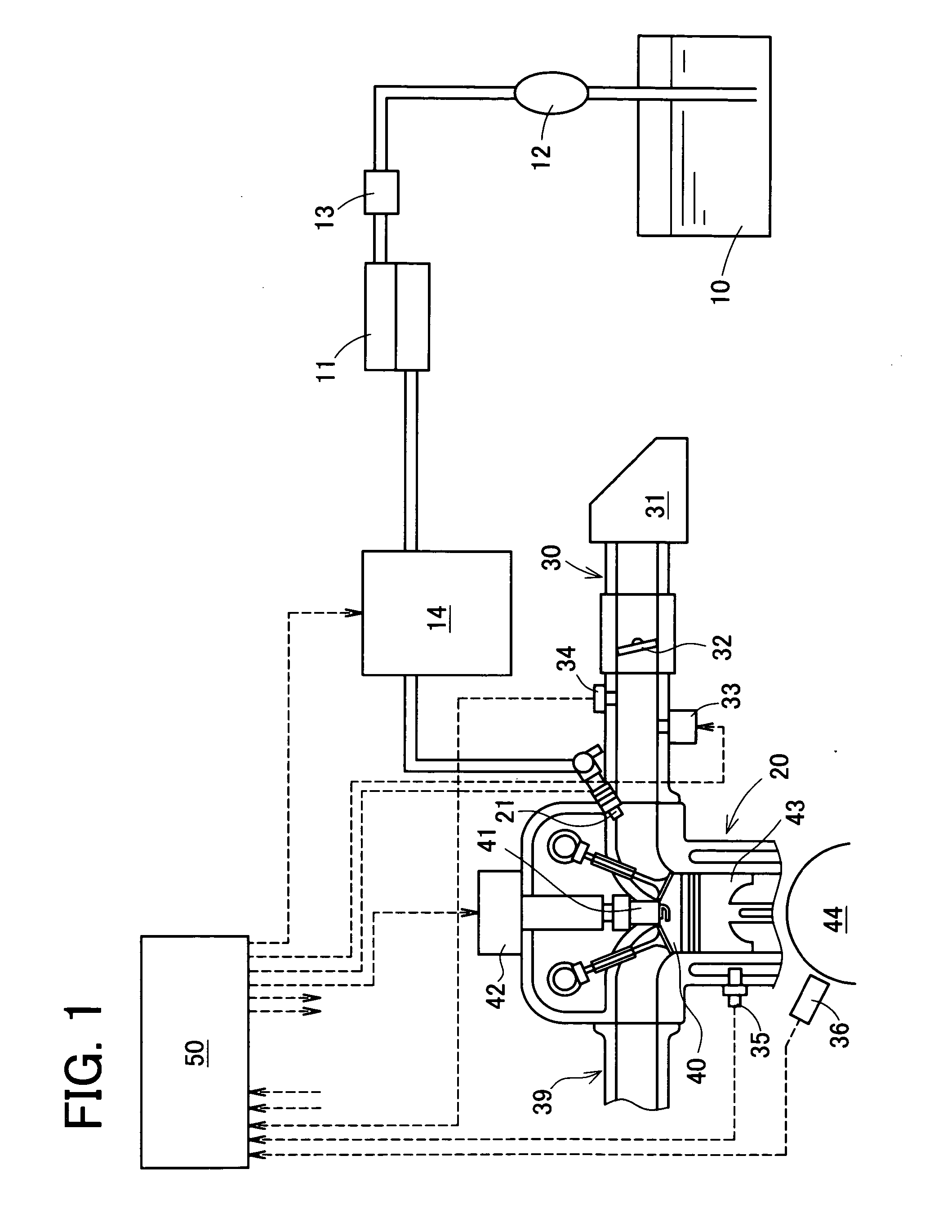
[0043]FIG. 1 is a schematic structural view of the engine system of the outboard engine in the present embodiment. This engine system includes a fuel tank 10 which therein stores fuel, a low-pressure pump 11 for sucking in the fuel from the fuel tank 10, and a priming pump 12 and a fuel filter 13 disposed between the fuel tank 10 and the low-pressure pump 11. Further, the engine system further includes a vapor separator 14 for temporarily storing the fuel fed therein from the low-pressure pump 11.

[0044] A reciprocating engine 20, which is an internal combustion engine, is provided with a fuel injecting valve (an injector) 21 which is supplied with fuel from the vapor separator 14. The supplied fuel is injected into an intake passage 30 by ac...


PUM


Abstract

With a low-pressure pump, fuel is supplied to a vapor separator comprising an air discharge port and a ball valve for closing the air discharge port in association with a rise in fluid level of the fuel supplied to the vapor separator. When the fuel is filled into the vapor separator entirely, the ball valve acts to tightly close the vapor separator, thereby pressurizing the fuel in the vapor separator.

Description

BACKGROUND OF THE INVENTION [0001] 1. Field of the Invention [0002] The present invention relates to a fuel supply apparatus and a vapor separator in an outboard engine provided with a fuel injection system. [0003] 2. Description of Related Art [0004] Conventionally, an engine provided with a fuel injection system is constructed to be supplied with a predetermined amount of fuel by means of an injector placed in an intake passage and an electrically controlled fuel pump and a predetermined amount of air supplied under the control of a throttle valve. A fuel supply apparatus in an outboard engine provided with a fuel tank mounted on a ship's body needs a long pipe for fuel supply to connect the tank to the engine. A vapor separator serving as an auxiliary, tank is therefore disposed near the engine. [0005] An example of the above fuel supply apparatus in the outboard engine is disclosed in Japanese patent unexamined publication No. 2001-140720. This fuel supply apparatus includes a f...

Claims


Application Information

Patent Timeline
Patent Type & Authority Applications(United States)
IPC IPC(8): F02B61/04F02M37/00F02M37/20
CPCF02B61/045F02M37/20F02M37/007F02M37/0058
Inventor HAMADA, MIKIONUNOME, HIROYUKI
Owner AISAN IND CO LTD
Why Eureka
Try Eureka