Keyed latch valve for fuel filter

Inactive Publication Date: 2005-01-06
PARKER INTANGIBLES LLC
View PDF15 Cites 59 Cited by
  • Summary
  • Abstract
  • Description
  • Claims
  • Application Information

AI Technical Summary

Benefits of technology

[0026] Once a filter element with a proper selection of keys is installed in the housing, fluid can be provided into the housing and pass through the filter media ring to be filtered. When the element is to be replaced, the spring assists in removing the element from the housing, and returns the valve device to a position blocking the opening in the pipe. This prevents unfiltered fuel and contaminants from passing through the pipe and downstream in the system. The location of the opening in the lower end of the pipe is below the typical level of fuel in the housing, which prevent

Problems solved by technology

However, problems may arise when such filter elements are replaced.
One problem is that filter elements with different sizes and/or filtration capabilities often have identical mounting configurations and can fit on the same filter head.
However, use of the wrong filter can cause poor engine performance and allow undesirable amounts of contaminants to pass through the fuel system.
Another problem is that individuals may remove a spent filter element and simply re-attach the housing portions without a fresh element.
While the engine may operate (at least for a short period of time), this can be detrimental to the engine.
A still furthe

Method used


Image

  • Keyed latch valve for fuel filter
  • Keyed latch valve for fuel filter
  • Keyed latch valve for fuel filter

Examples


first embodiment

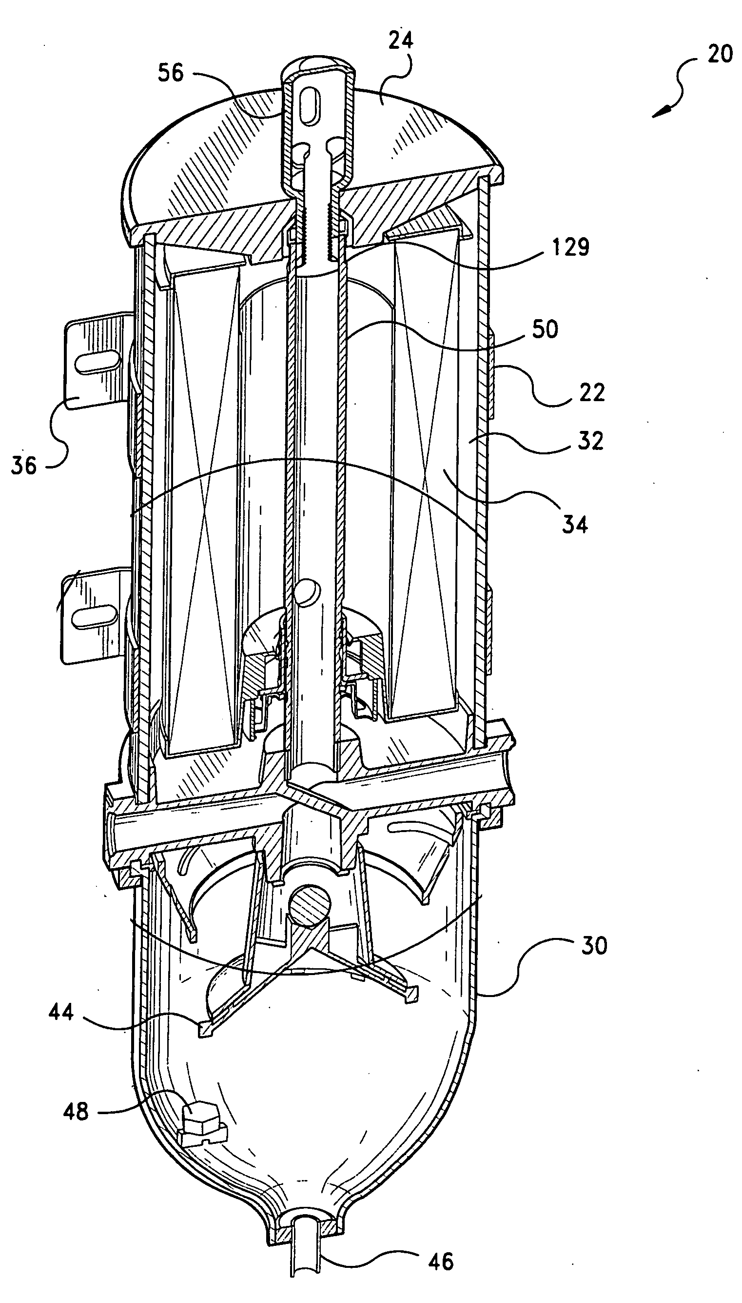
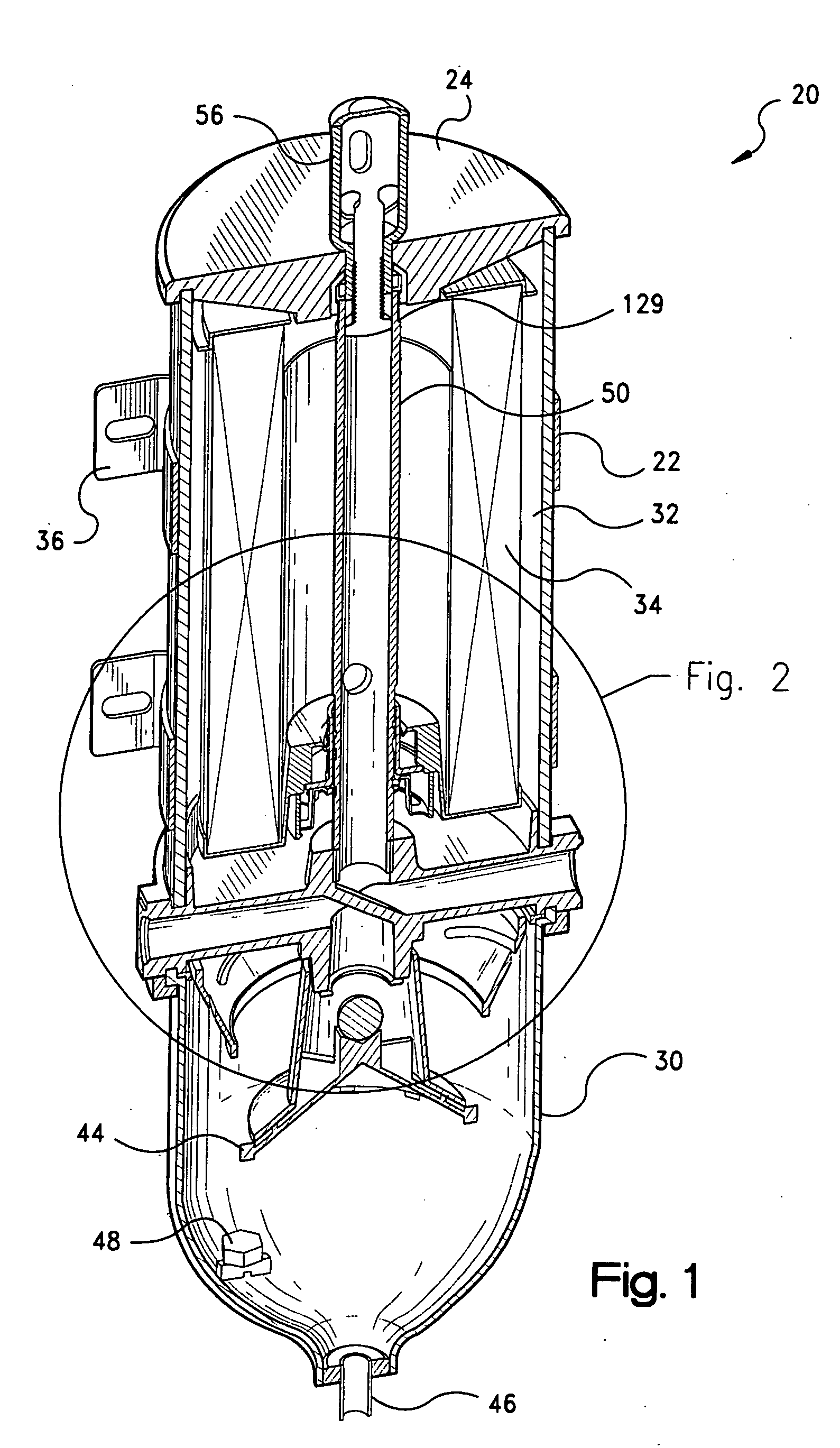
[0076] A filter element 140 is mounted within the housing portions and comprises a ring-shaped media circumscribing a central cavity 141. Filter element 140, similar to filter element 92 in the first embodiment, can be any filter media appropriate for the particular application, and includes an upper or first annular end cap 142 and a lower or second annular end cap 143. The end caps 142, 143 are bonded to the media in an appropriate manner. The filter element 140 is supported on a series of flanges or ribs 144 integral with the lower housing portion.

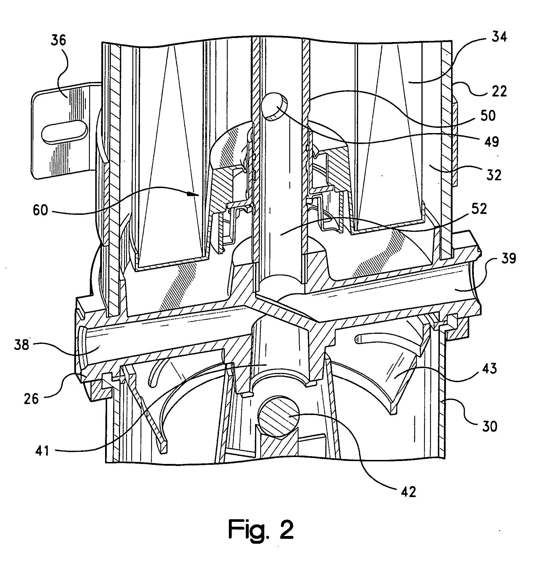
[0077] A pump assembly, indicated generally at 148, is also mounted between the housing portions, and includes an electric pump 150 with integrated drive motor, and an upper cap or cover 152 having an electrical connection 154 for the motor. Pump 150 can be any conventional type of pump appropriate for the particular application. One such pump is available from AIRTEX PRODUCTS of Fairfield, Ill., with a flow rate of 110 Liters / Minute at...

second embodiment

[0103] As described above with respect to FIG. 16, the keys 194 of the key device, and the tabs 76 and slots 78 on the latch device 64 are arranged such that when the filter element is inserted into the housing, at least a portion of the keys can fit through the slots 78. The axially longer and radially thinner portions 240 of the keys fit through the slots 78 in the latch device and engage the engagement surface 86 of the sleeve 84 on the valve device. Similar to the second embodiment, as the element is inserted upwardly into the housing, the keys press against the sleeve 84, and cause the latch device to bend and pull the fingers 80 radially outward from the inlet pipe. As the fingers are pulled outward, the distal ends 82 of the fingers are pulled outward from locking groove 167, thus releasing the latch device and allowing the latch device to slide axially upward along the inlet pipe.

[0104] Simultaneously with the fingers 80 being released, the radially wider and axially shorter...


PUM

PropertyMeasurementUnit
Lengthaaaaaaaaaa
Diameteraaaaaaaaaa
Widthaaaaaaaaaa

Abstract

A fuel filter includes mating housing portions defining an interior cavity. A pipe in the housing includes a central flow passage with an opening along the length of the pipe, and an exterior groove. A latch device with discrete fingers closely surrounds the pipe and is engageable with the groove to prevent the latch device (68) from moving axially along the pipe. The latch device has an annular sleeve, radially-outwardly spaced from the fingers. A moveable valve device surrounds the pipe and has a valve sleeve normally covering the opening in the pipe. An annular base on the sleeve includes radially projecting tabs defining a plurality of slots. A filter element is removeably located in the housing and has an end cap with a valve actuating portion. The valve actuating portion includes a cylindrical portion and an annular base projecting radially inward from the cylindrical portion. The valve actuating portion includes a plurality of thin, flat keys spaced around the annular base and projecting radially inward from the cylindrical portion and axially outward from the base. The keys have first portions which project through the slots in the valve device and engage the sleeve of the latch device to unlock the latch device from the pipe, and second portions which engage the base of the valve device and move the valve device to uncover the opening in the pipe, when the filter element is inserted into the housing.

Description

CROSS REFERENCE TO RELATED APPLICATION [0001] This application is a divisional of U.S. patent application Ser. No. 10 / 129,350 filed on May 2, 2002, which is a national phase application under 35 U.S.C. § 371 of International Application No. PCT / US00 / 31329 filed on Nov. 15, 2000 and which designated the United States, and which claims priority to U.S. Provisional Patent Application Ser. No. 60 / 168,941 filed on Dec. 3, 1999 and U.S. patent application Ser. No. 09 / 452,857 filed on Dec. 3, 1999, now U.S. Pat. No. 6,495,042, the disclosures of which are incorporated herein by reference.FIELD OF THE INVENTION [0002] This invention relates to fluid filters, and more particularly to fuel filters for vehicles. BACKGROUND OF THE INVENTION [0003] Many types of fuel filters (also referred to as “separators”) are known in the prior art. A popular type of fuel filter has a housing that encloses a replaceable ring-shaped filter element. The filter element ensures that impurities are removed from f...

Claims


Application Information

Patent Timeline
IPC IPC(8): B01D29/15B01D35/153B01D36/00F02M37/22
CPCB01D29/15B01D35/153F02M2037/225F02M37/22B01D2201/4084B01D2201/4046B01D2201/34B01D2201/162B01D36/003B01D35/1576B01D35/1573B01D29/21B01D29/902B01D29/925B01D29/96B01D35/157B01D35/18B01D35/26F02M37/26F02M37/30F02M37/34F02M37/42F02M37/44F02M37/46F02M37/48
Inventor KNIGHT, STEVEN R.
Owner PARKER INTANGIBLES LLC
Why Eureka
Try Eureka