Core bar for rubber crawler and rubber crawler

a technology of rubber crawler and core bar, which is applied in the direction of endless track vehicles, vehicles, transportation and packaging, etc., can solve the problems of large noise, noise and vibration, damage to the overhanging part or the rolling wheel, etc., and achieve the effect of reducing height differences

Inactive Publication Date: 2005-01-06
SUMITOMO RUBBER IND LTD
View PDF7 Cites 7 Cited by
  • Summary
  • Abstract
  • Description
  • Claims
  • Application Information

AI Technical Summary

Benefits of technology

[0008] The present invention has been made to solve these kinds of problems in the related art. It is, therefore, an object of the present invention to provide a core bar for an outside rail type rubber crawler that is capable of reducing height differences between the adjacent overhanging parts and collisions between the rolling wheel and the overhanging part which are caused by sinking of the overhanging part due to a transfer of the rolling wheel from one overhanging part to the next one, and a rubber crawler in which such core bars are embedded.

Problems solved by technology

However, since the sinking of the overhanging part increases the height difference between the adjacent overhanging parts in the circumferential direction of the crawler and, when the rolling wheel is transferred to the next overhanging part, the rolling wheel collides with the next overhanging part causing noises and vibrations.
In particular, in a truck loader, a vibration roller, a bulldozer or the like, which mostly runs at comparatively high speeds, the collision of the rolling wheel with the overhanging parts tends to cause large noises and damages the overhanging part or the rolling wheel.

Method used


Image

  • Core bar for rubber crawler and rubber crawler
  • Core bar for rubber crawler and rubber crawler
  • Core bar for rubber crawler and rubber crawler

Examples


first embodiment

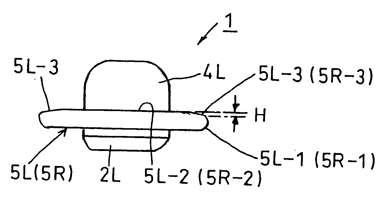
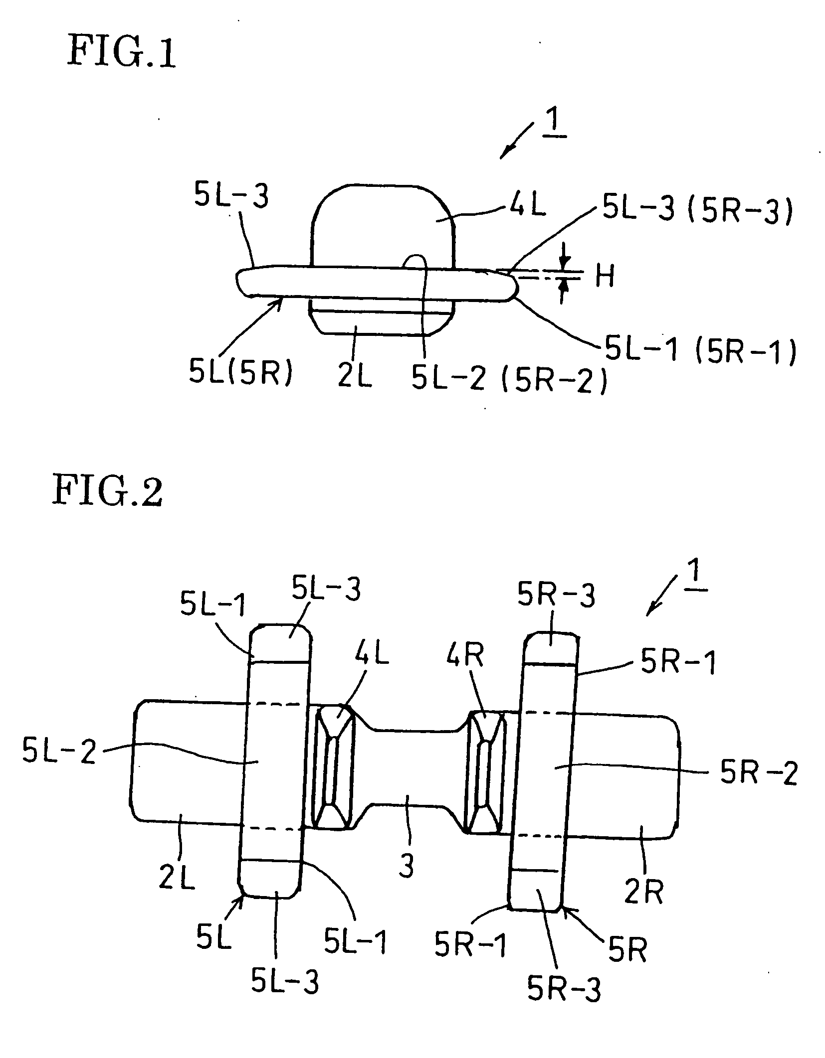
[0038]FIG. 1 and FIG. 2 show a core bar 1 for a rubber crawler in accordance with the present invention. The core bar 1 has right and left wing parts 2R, 2L that are formed in the shape of a plate or a belt and an engaging part 3 that connects the right and left wing parts 2R and 2L. On both the sides of the engaging part 3, protrusions 4R, 4L for guiding a rolling wheel are formed in a protruding manner. On both outer sides (right and left outsides) of the right and left protrusions 4R, 4L, right and left outside rails 5R, 5L having overhanging parts 5R-1, 5L-1 are formed to have a greater height than the right and left wing parts 2R, 2L in the thickness direction of the wing part.

[0039] The core bar 1 is formed of metal by the casting method or the forging method, or formed of metal or resin (preferably, with reinforced fiber) by the press-forming method.

[0040] In the core bar 1 of the first embodiment, the right and left outside rails 5R, 5L have flat rail surfaces 5R-2, 5L-2, r...

third embodiment

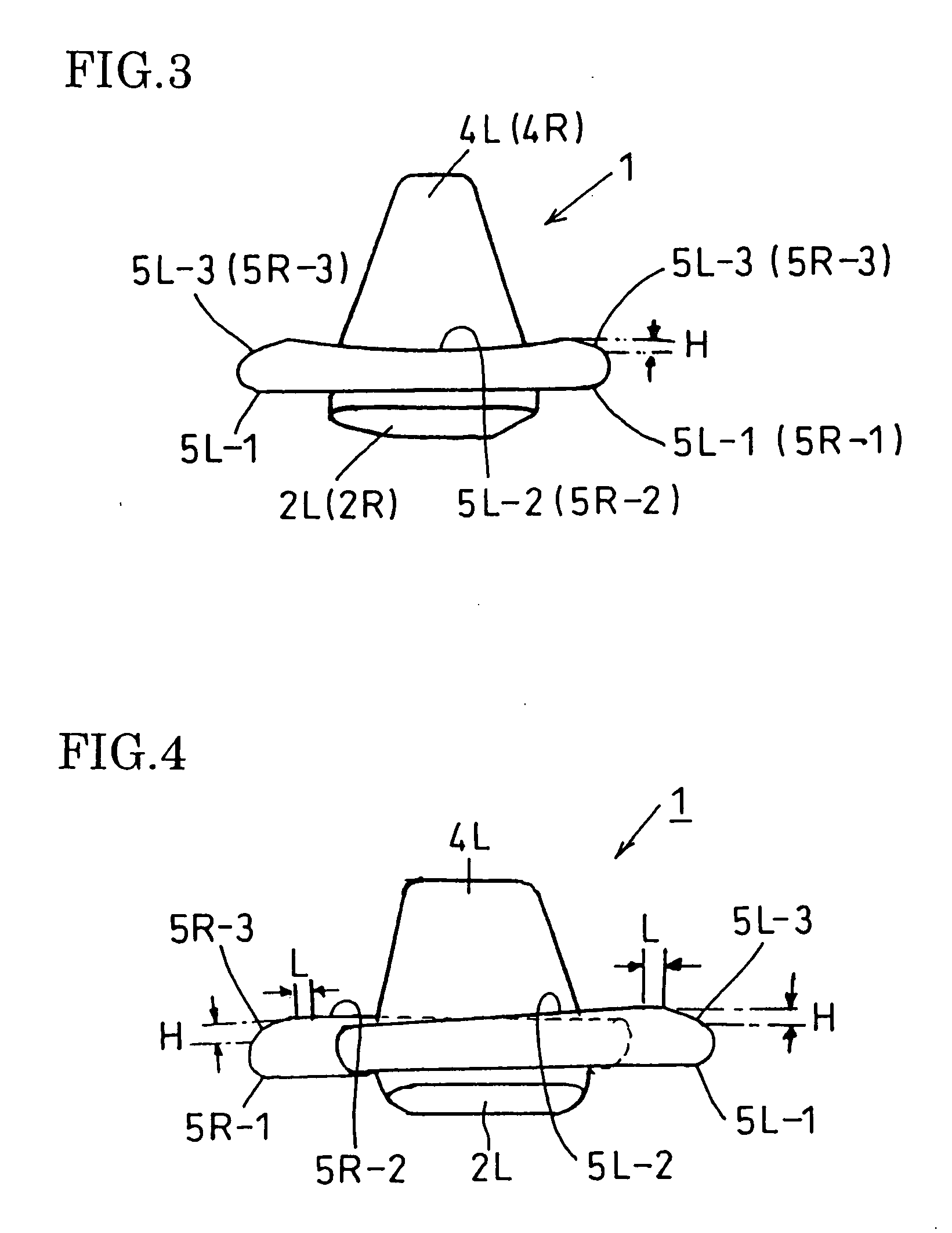
[0049] The core bars 1 of the third embodiment shown in FIG. 4 and FIG. 5 are arranged side by side on the belt-shaped rubber crawler body 6, as shown in FIG. 12, such that the right and left outside rails 5R, 5L are provided in a staggered arrangement in the right and left sides of the widthwise direction of the crawler, and the wing parts 2R, 2L are embedded in the rubber. Here, when viewed from the side, the rail surfaces 5R-2, 5L-2 including the slanting surfaces 5R-3, 5L-3 of the right and left outside rails 5R, 5L overlap each other, to constitute a rolling wheel track that is substantially continuous in the lengthwise direction of the crawler, thereby not only preventing a collision but also ensuring a smooth running performance by supporting the outside collars 8R, 8L with one of the right and left tracks when the rolling wheel is transferred to the next rail surface.

[0050] The slanting surfaces 5R-3, 5L-3 on the edge portions of the overhanging parts 5R-1, 5L-1 extending fr...

second embodiment

[0051] The core bar 1 shown in FIG. 6 is a modification of the second embodiment described above with reference to FIG. 3. The right and left rail surfaces 5R-2, 5L-2, each formed by a concave surface, are continuous with the downwardly slanting surfaces 5R-3, 5L-3 formed on the edge portions of the overhanging parts 5R-1, 5L-1 in the front-rear direction via flat surfaces L, and the core bars 1 shown in FIG. 6 are also embedded in the rubber crawler body 6 in the state shown in FIG. 11. Between the rail surfaces 5R-2, 5L-2 and the slanting surfaces 5R-3, 5L-3 are formed flat surfaces L, respectively.

[0052] The core bar 1 shown in FIG. 7 is a modification of the third embodiment described above with reference to FIG. 4 and FIG. 5. The right and left rail surfaces 5R-2, 5L-2 are formed by flat surfaces within the width of the wing parts 2R, 2L, and the rail surfaces of the overhanging parts 5R-1, 5L-1 extending on the opposite sides are formed nearly in the shape of a hill having an ...


PUM


Abstract

A core bar for a rubber crawler includes: right and left wing parts; an engaging part for connecting the wing parts; right and left protrusions to guide a rolling wheel; and right and left outside rails that are formed on outer sides of the right and left protrusions, respectively, and have overhanging parts extending in the widthwise direction of the wing part. The overhanging part is formed on an edge portion thereof with a surface that slants downward from a top surface of the outside rail.

Description

BACKGROUND OF THE INVENTION [0001] 1. Field of the Invention [0002] The present invention relates to a core bar for a rubber crawler and a rubber crawler used for a farm machine, a construction machine and the like and, to be more specific, to an outside rail type rubber crawler. [0003] 2. Description of the Related Art [0004] In Japanese Examined Utility Model Publication No. HEI 7-17658, there is proposed a core bar for a rubber crawler having a pair of angular protruding parts (protrusions for preventing the coming-off of a rolling wheel) formed on both sides of an engaging part at the center between right and left wing parts, on outer side of each of the angular parts described above is formed a shoulder part (outside rail) elevated with respect to the wing parts of the core bar, wherein the respective shoulder parts are formed with overhanging parts that overhang in the front-rear direction (in the widthwise direction of the wing part), and wherein the top surfaces of the respe...

Claims


Application Information

Patent Timeline
Patent Type & Authority Applications(United States)
IPC IPC(8): B62D55/20B62D55/253B62D55/24
CPCB62D55/24B62D55/202
Inventor UENO, YOSHIO
Owner SUMITOMO RUBBER IND LTD
Why Eureka
Try Eureka