
Drill string rotation encoding

a drilling string and rotation coding technology, applied in the field of drilling wells, can solve the problems of increasing the likelihood of drilling string irretrievably lodged in the borehole, affecting the accuracy of drilling, so as to reduce the likelihood of transmission errors and quick and accurate communication

Active Publication Date: 2005-01-06
SCHLUMBERGER TECH CORP
View PDF9 Cites 63 Cited by
  • Summary
  • Abstract
  • Description
  • Claims
  • Application Information

AI Technical Summary

Benefits of technology

[0008] Exemplary embodiments of the present invention may advantageously provide several technical advantages. For example, exemplary methods according to this invention provide for quick and accurate communication with a downhole tool, such as a sensor or a downhole drilling tool. Aspects of this invention are particularly advantageous in that the surface to downhole communication may be accomplished without substantially interrupting the drilling process. Rather, data and / or commands may be encoded in rotation rate variations in the drill string and transmitted downhole during drilling. Moreover, aspects of this invention may be utilized in combination with conventional downhole communication techniques. For example, in one embodiment, MWD data may be receive via conventional mud pulse telemetry techniques and utilized in steering decisions. Commands may then be encoded in a sequence of various drill string rotation variables and transmitted downhole to a directional drilling tool.

Problems solved by technology

In such applications, reliable and accurate data transmission is important as errors in command interpretation by the downhole drilling hardware may cause considerable difficulties.
Such techniques tend to be disadvantageous since each time the drilling operation is stopped valuable rig time is lost.
Moreover, stopping the drill string increases the likelihood that it becomes irretrievably lodged in the borehole.

Method used


Image

  • Drill string rotation encoding
  • Drill string rotation encoding
  • Drill string rotation encoding

Examples


Embodiment Construction

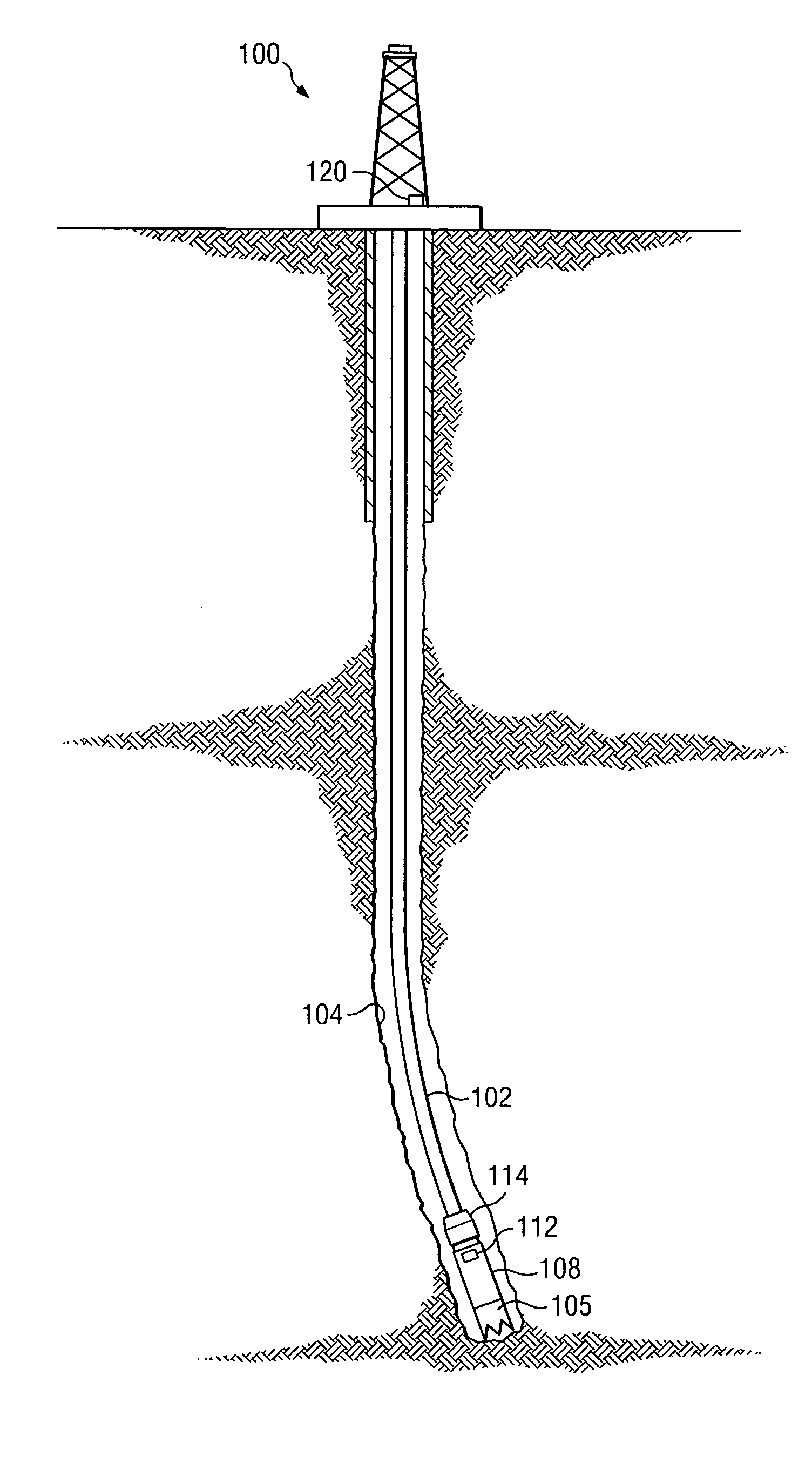
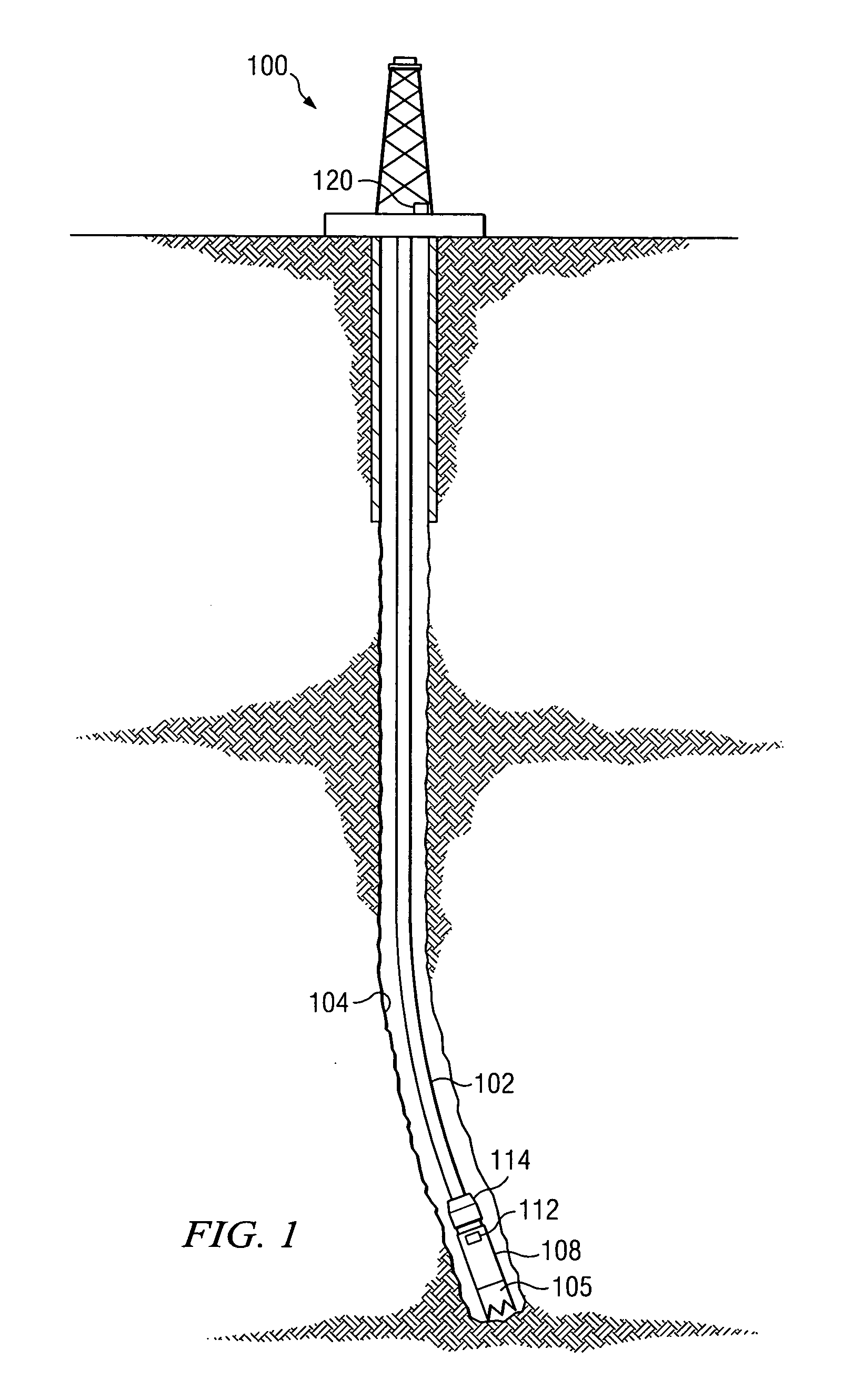
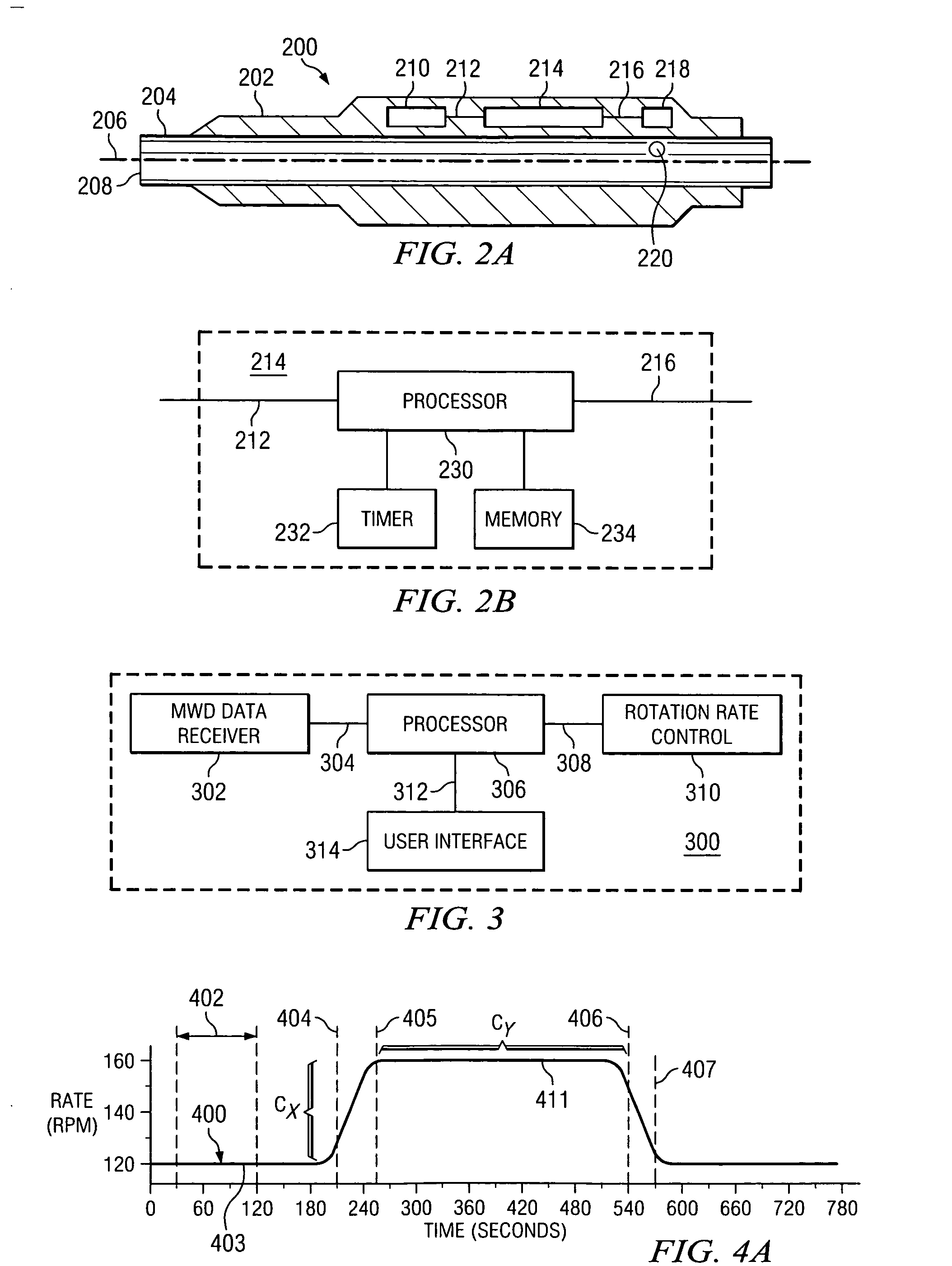
[0020]FIG. 1 depicts a diagram representing an exemplary drilling rig 100 on which the methods and apparatus of the present invention may be deployed. Drill string 102 comprises a plurality of sections of elongated drill pipe and is shown within a borehole 104. The distal end of the drill string 102 includes a drill bit 105 for drilling the borehole 104. Drill string 102 further comprises a downhole device 108 that is adapted to receive data transmitted from the surface, the data encoded as a sequence of rotation rate variations of the drill string 102 in accordance with the present invention. As described in more detail below with respect to FIGS. 2A and 2B, downhole device 108 includes a sensor for measuring the rotation rate of the drill string 102. Downhole device 108 may further optionally include a trajectory control mechanism that is responsive to commands transmitted from the surface to direct the projected path of the borehole 104 during drilling. Downhole device 108 may al...


PUM


Abstract

A method for communicating with a downhole device is provided. The method includes predefining an encoding language including codes understandable to the device, the codes represented in the language as predefined value combinations of drill string rotation variables such as rotation rate or duration. The method further includes rotating a drill string at first and second rates and measuring the rotation rates downhole. The first measured rotation rate is processed downhole in combination with the second measured rotation rate to acquire a code in the language at the downhole device. Embodiments of the invention are useful, for example, for transmitting commands from the surface to a downhole device such as a directional drilling tool. Exemplary embodiments of this invention advantageously provide for quick and accurate communication with a downhole device without substantially interrupting the drilling process.

Description

RELATED APPLICATIONS [0001] This application claims the benefit of U.S. Provisional Application Ser. No. 60 / 484,042 entitled Encoding Data in a Sequence of Rotational Speed Variations of a Drill String, filed Jul. 1, 2003.FIELD OF THE INVENTION [0002] This invention, in exemplary embodiments, relates to the field of oil well drilling, and in particular, to methods and apparatus for communicating information between the surface and a downhole device and more particularly, to methods and apparatus for encoding information in predefined sequences of varying rotation rates of the drill string. BACKGROUND OF THE INVENTION [0003] Oil and gas well drilling operations commonly include the use of sensors deployed downhole as a part of the drill string to acquire data as the well bore is being drilled. This real-time data may provide information about the progress of the drilling operation and the earth formations surrounding the well bore. Significant benefit may be obtained by improved cont...

Claims


Application Information

Patent Timeline
IPC IPC(8): E21B47/12G01V11/00
CPCG01V11/002E21B47/12E21B47/16
Inventor BARON, EMILIOJONES, STEPHEN
Owner SCHLUMBERGER TECH CORP
Learn More