
Programming method for controlling a downhole steering tool

a programming method and steering tool technology, applied in the direction of directional drilling, surveying, borehole/well accessories, etc., can solve the problems of non-uniform drill string rotation rate and sometimes difficult precise measurement of drill string rotation rate, so as to reduce the quantity of encoded information, increase bandwidth, and communicate quickly and accurately

Active Publication Date: 2007-05-29
SCHLUMBERGER TECH CORP
View PDF22 Cites 37 Cited by
  • Summary
  • Abstract
  • Description
  • Claims
  • Application Information

AI Technical Summary

Benefits of technology

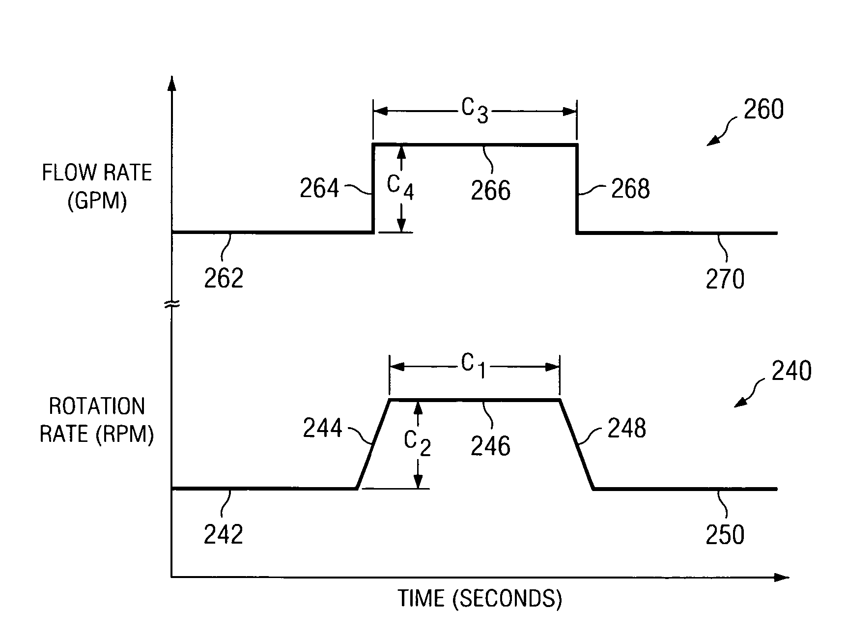
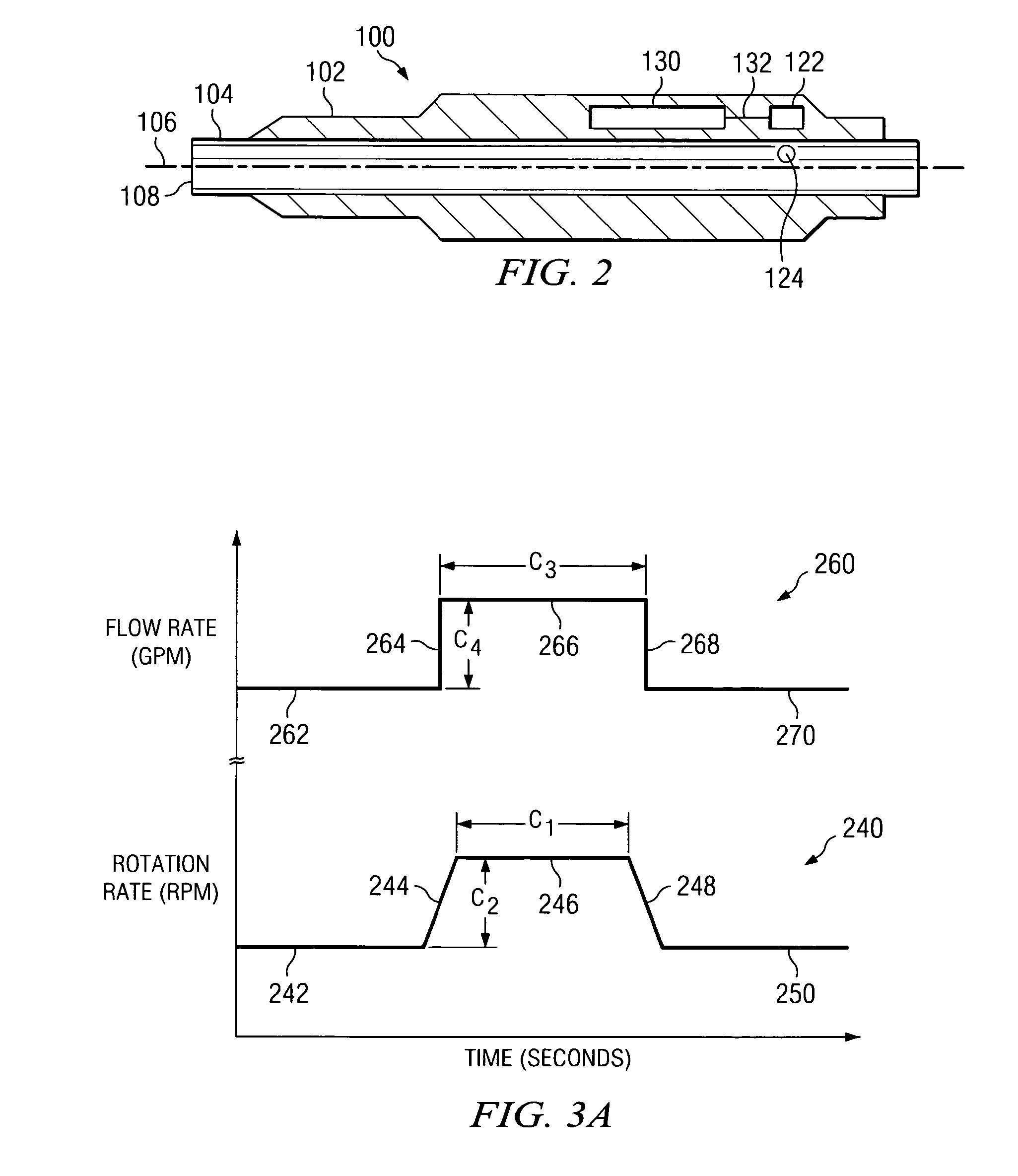
[0008]Exemplary embodiments of the present invention may advantageously provide several technical advantages. For example, exemplary methods according to this invention provide for quick and accurate communication with a downhole tool, such as a sensor or a downhole drilling tool. In particular, the use of both rotation rate and flow rate encoding tends to provide for increased bandwidth as compared to prior art encoding methods. Moreover, the use of a differential encoding scheme, in which a relative change in the value of a tool parameter is encoded, may also be advantageous. Such a differential approach tends to reduce the quantity of encoded information and thereby may further reduce transmission time as compared to the prior art.
[0009]The use of a differential encoding scheme may also be advantageous in that it tends to require fewer distinct commands than direct programming methods of the prior art. As such, fewer rotation rate and / or flow rate levels are required to encode those commands, which tends to increase accuracy by decreasing the likelihood of transmitting erroneous commands. Moreover, having fewer rotation rate levels may be advantageous in certain applications in which accurate measurement of the rotation rate is problematic (e.g., in stick / slip situations, as described above).

Problems solved by technology

This is a condition commonly referred to in the art as stick / slip, and is known to cause a non-uniform drill string rotation rate.
In stick / slip situations, precise measurement of the drill string rotation rate sometimes becomes problematic.

Method used


Image

  • Programming method for controlling a downhole steering tool
  • Programming method for controlling a downhole steering tool
  • Programming method for controlling a downhole steering tool

Examples


Embodiment Construction

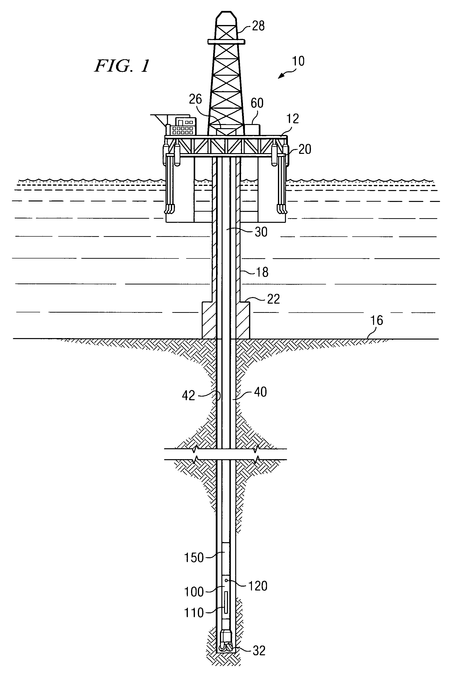
[0021]FIG. 1 illustrates a drilling rig 10 suitable for utilizing exemplary embodiments of the present invention. In FIG. 1, a semisubmersible drilling platform 12 is positioned over an oil or gas formation (not shown) disposed below the sea floor 16. A subsea conduit 18 extends from deck 20 of platform 12 to a wellhead installation 22. The platform may include a derrick 26 and a hoisting apparatus 28 for raising and lowering the drill string 30, which, as shown, extends into borehole 40 and includes a drill bit 32 and a directional drilling tool 100 (such as a three dimensional rotary steerable tool). Rig 10 further includes a transmission system 60 for controlling, for example, the rotation rate of drill string 30 and the flow rate of drilling fluid in drill string 30. Such devices may be computer controlled or manually operated as described in more detail below. The invention is not limited in this regard.

[0022]In the exemplary embodiment shown, directional drilling tool 100 incl...


PUM


Abstract

A method for communicating with a downhole tool located in a subterranean borehole is disclosed. Exemplary embodiments of the method include encoding data and / or commands in a sequence of varying drill string rotation rates and drilling fluid flow rates. The varying rotation rates and flow rates are measured downhole and processed to decode the data and / or the commands. In one exemplary embodiment, commands in the form of relative changes to current steering tool offset and tool face settings are encoded and transmitted downhole. Such commands may then be executed, for example, to change the steering tool settings and thus the direction of drilling. Exemplary embodiments of this invention advantageously provide for quick and accurate communication with a downhole tool.

Description

RELATED APPLICATIONS[0001]None.FIELD OF THE INVENTION[0002]The present invention relates generally to a method of communicating information from the surface to a downhole device located in a subterranean borehole. More particularly, exemplary embodiments of this invention relate to a method of encoding tool commands in a combination of drill string rotation rate and drilling fluid flow rate variations. Exemplary embodiments of the invention also relate to a differential programming method in which relative changes to current tool parameters are encoded.BACKGROUND OF THE INVENTION[0003]Oil and gas well drilling operations commonly use sensors deployed downhole as a part of the drill string to acquire data as the well bore is being drilled. This real-time data may provide information about the progress of the drilling operation or the earth formations surrounding the well bore. Significant benefit may be obtained by improved control of downhole sensors from the rig floor or from remot...

Claims


Application Information

Patent Timeline
Patent Type & Authority Patents(United States)
IPC IPC(8): E21B44/00E21B7/04
CPCE21B47/12E21B47/16E21B47/18
Inventor JONES, STEPHENSUGIURA, JUNICHI
Owner SCHLUMBERGER TECH CORP
Learn More