
Pump drive motor control apparatus

a technology of motor control and push rod, which is applied in the direction of push control, positive displacement liquid engine, electrical apparatus, etc., can solve the problems of reducing the above-described operation sound, the antilock brake system cannot achieve the control of the brake fluid pressure, and the rotational speed of the motor cannot be changed, so as to achieve the effect of increasing the rotational speed of the motor, increasing the priority, and increasing the threshold

Inactive Publication Date: 2005-01-06
ADVICS CO LTD
View PDF9 Cites 4 Cited by
  • Summary
  • Abstract
  • Description
  • Claims
  • Application Information

AI Technical Summary

Benefits of technology

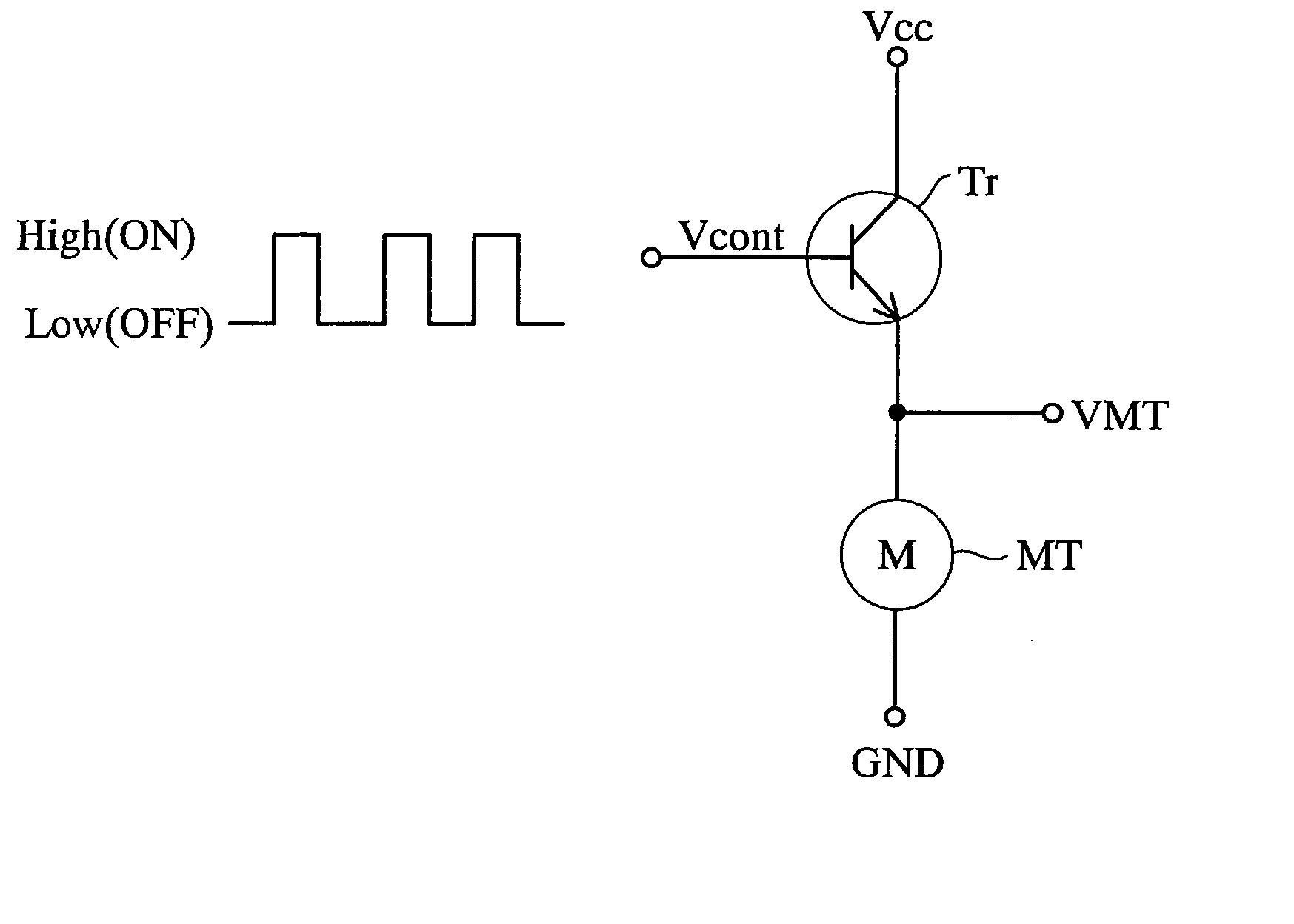
[0009] An object of the present invention is to provide a pump drive motor control apparatus for controlling the rotational speed of a motor for driving a pump, which apparatus can simultaneously attain reduction of operation sound of the motor and securing of a required discharge flow rate of the pump.
[0012] By virtue of the above configuration, the threshold can be increased with the quantity of working fluid which the pump is required to discharge (e.g., a required discharge flow rate of the pump). As a result, the motor (and the pump) can be controlled such that its rotational speed increases with the required discharge flow rate of the pump. Accordingly, reduction of the operation sound of the motor and securing of the required discharge flow rate can be attained simultaneously.
[0015] By virtue of the above configuration, since the threshold can be changed in accordance with the “value varying in accordance with road surface conditions,” the rotational speed of the motor can be changed in accordance with the conditions of a road surface on which the vehicle travels. Accordingly, as described above, it becomes possible to simultaneously achieve reduction of the operation sound of the motor and avoidance of failure of the ABS control.
[0016] Preferably, the threshold changing means is configured to change the threshold on the basis of deceleration of the vehicle body during a period in which the brake fluid pressure controller is operating, the deceleration serving as the value varying in accordance with road surface conditions. The deceleration of the vehicle body can be obtained (estimated) on the bases of a wheel speed sensor for detecting wheel speed of each wheel of the vehicle. In the antilock brake system, since the wheel speed of each wheel of the vehicle must be obtained in order to perform ABS control, the wheel speed sensor is an essential component. Accordingly, the above-described configuration simultaneously achieves reduction of the operation sound of the motor and avoidance of failure of the ABS control, by use of an inexpensive configuration, without addition of dedicated sensors or the like for changing the threshold.
[0018] In general, during travel on a poor road, the flow rate of brake fluid returned to the reservoir tends to increase. Therefore, the rotational speed of the motor is desirably increased with higher priority imparted to avoidance of failure of ABS control. When the threshold changing means is configured to change the threshold on the basis of the value representing the degree of road surface roughness, the threshold can be increased with the degree of road surface roughness. As a result, the rotational speed of the motor (and the pump) can be increased when the degree of road surface roughness exceeds a predetermined level. Accordingly, failure of ABS control, which would otherwise occur during travel on a poor road, can be avoided without fail.

Problems solved by technology

Moreover, if the reservoir is filled with brake fluid, further return of brake fluid from the hydraulic circuit of the antilock brake system to the reservoir becomes impossible, resulting in failure of the antilock brake system to attain brake fluid pressure control (hereinafter, referred to as “ABS control”).
However, in the disclosed apparatus, since the above-described threshold is fixed, the rotational speed of the motor cannot be changed in accordance with the road surface condition, with the result that the above-described reduction of operation sound and the above-described avoidance of failure of the ABS control cannot be achieved at the same time.
In other words, the conventional control apparatus has a drawback in that reduction of operation sound of the motor (and the pump) and securing of a required discharge flow rate of the pump cannot be achieved at the same time.

Method used


Image

  • Pump drive motor control apparatus
  • Pump drive motor control apparatus
  • Pump drive motor control apparatus

Examples


Embodiment Construction

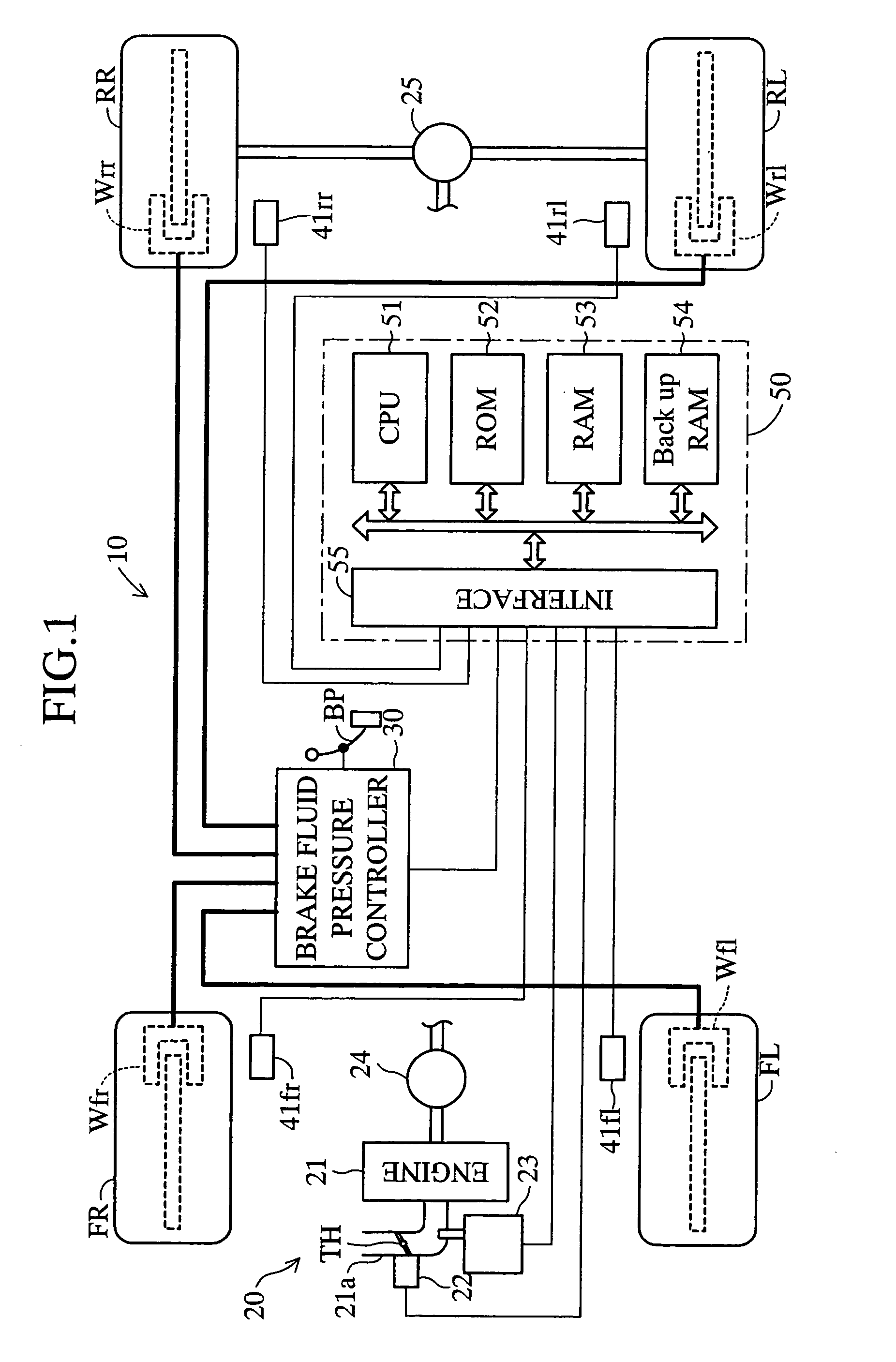
[0029] An embodiment of a pump drive motor control apparatus according to the present invention will be described with reference to the drawings. FIG. 1 schematically shows the structure of a vehicle equipped with a vehicle control apparatus 10 including a pump drive motor control apparatus according to the embodiment of the present invention. The illustrated vehicle is a four-wheel, rear-wheel drive (FR) vehicle having two front wheels (a front left wheel FL and a front right wheel FR) which are non-drive wheels (follower wheels), and two rear wheels (a rear left wheel RL and a rear right wheel RR) which are drive wheels.

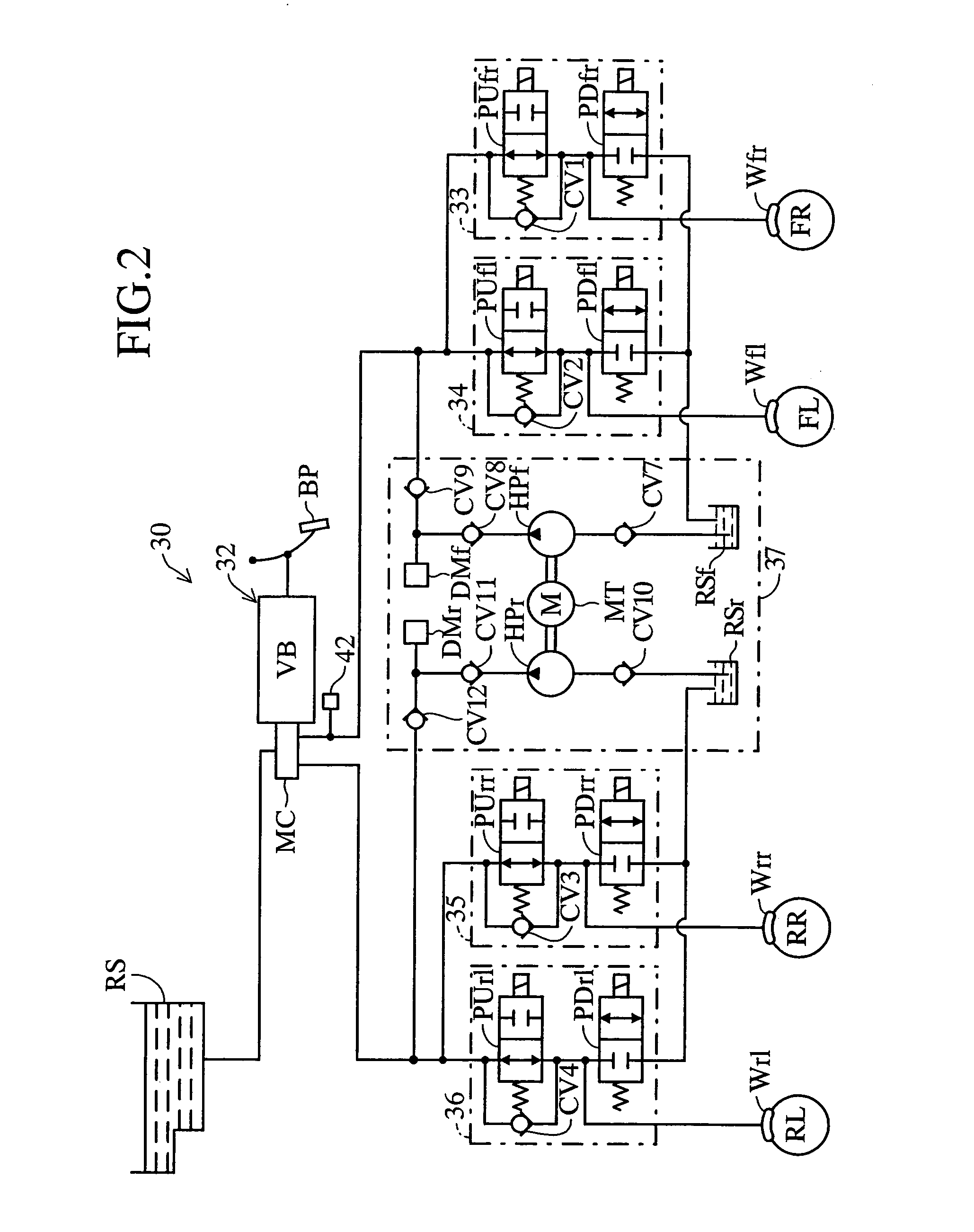
[0030] This vehicle control apparatus 10 has a drive force transmission mechanism 20 which generates a drive force and transmits it to the drive wheels RL and RR; and a brake fluid pressure controller 30 for generating a braking force in each wheel by means of brake fluid pressure.

[0031] The drive force transmission mechanism 20 comprises an engine 21 which gener...


PUM


Abstract

A pump drive motor control apparatus is applied to a motor for driving a hydraulic pump which pumps brake fluid returned to a reservoir as a result of ABS control and supplies the pumped brake fluid to a hydraulic circuit. When a motor inter-terminal voltage becomes equal to or less than a voltage threshold in a period during which a motor control signal is at a low level (supply of electricity to the motor is stopped), the control apparatus changes the motor control signal to a high level (resumes the supply of electricity) for a predetermined time, to thereby control the rotational speed of the motor. The control apparatus reduces the rotational speed of the motor by lowering the voltage threshold, which affects the rotational speed of the motor, with the vehicle body deceleration during ABS control, which corresponds to the friction coefficient of road surface, which determines the required discharge flow rate of the hydraulic pump.

Description

BACKGROUND OF THE INVENTION [0001] 1. Field of the Invention [0002] The present invention relates to a pump drive motor control apparatus for controlling the rotational speed of a motor for driving a pump, and more particularly to a pump drive motor control apparatus which controls the rotational speed of a motor through on-off control performed such that supply of electricity to the motor is resumed on the basis of a result of comparison between a predetermined threshold and a voltage which the motor generates during a period in which supply of electricity to the motor is stopped. [0003] 2. Description of the Related Art [0004] A conventional pump drive motor control apparatus of such a type is disclosed in, for example, Japanese kohyo (PCT) Patent Publication No. 2002-506406. The disclosed control apparatus is applied to a motor for driving a hydraulic pump which is used in an antilock brake system in order to pump brake fluid returned to a reservoir as a result of operation of th...

Claims


Application Information

Patent Timeline
IPC IPC(8): B60T8/48B60T8/40B60T17/02F04B49/06H02H7/08
CPCB60T8/404
Inventor KOKUBO, KOICHI
Owner ADVICS CO LTD
Learn More