
Integrated electromechanical arrangement and method of production

a technology of electromechanical arrangement and production method, which is applied in the direction of laminating printed circuit boards, emergency connections, instruments, etc., can solve the problems of limiting the freedom to design differentiated keypad layouts, difficult to change the layout of keypads without changing the engine pwb, etc., to facilitate customizability and upgradability

Active Publication Date: 2005-01-06
NOKIA TECHNOLOGLES OY
View PDF5 Cites 46 Cited by
  • Summary
  • Abstract
  • Description
  • Claims
  • Application Information

AI Technical Summary

Benefits of technology

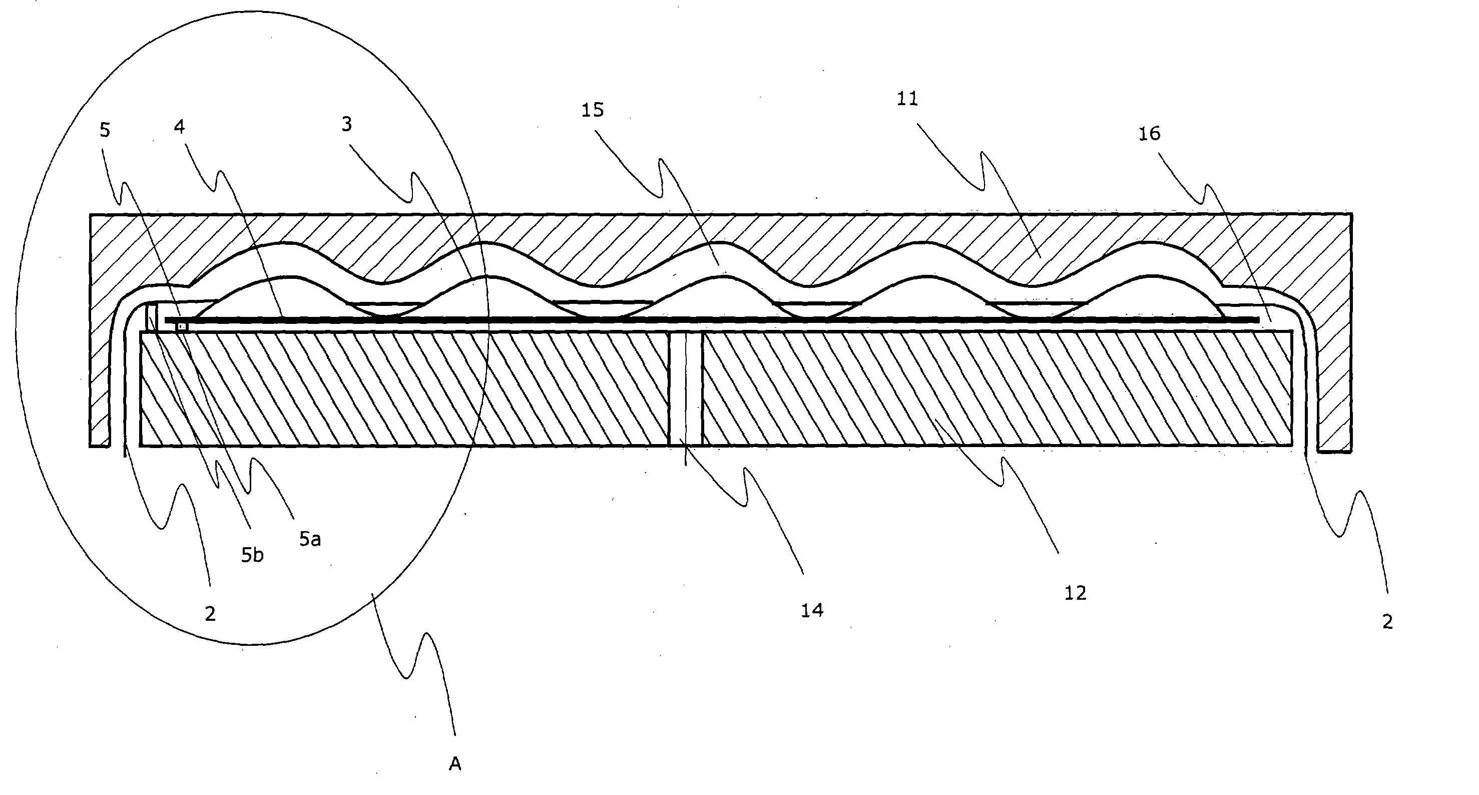
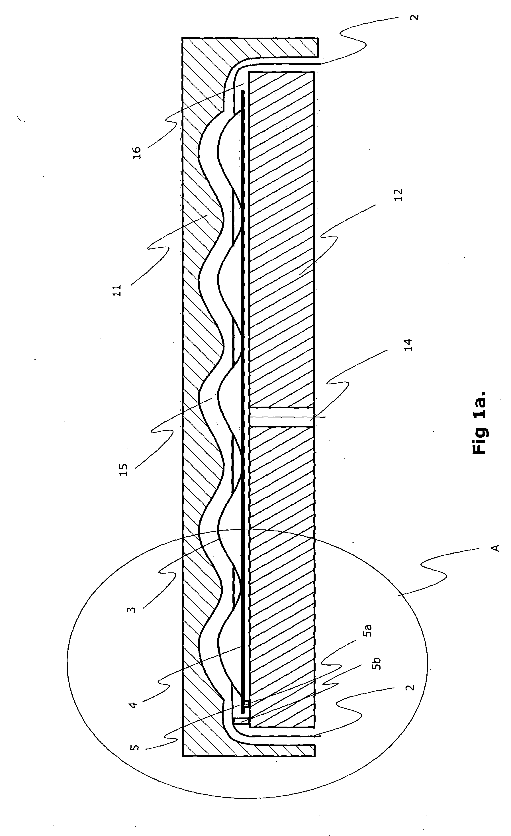
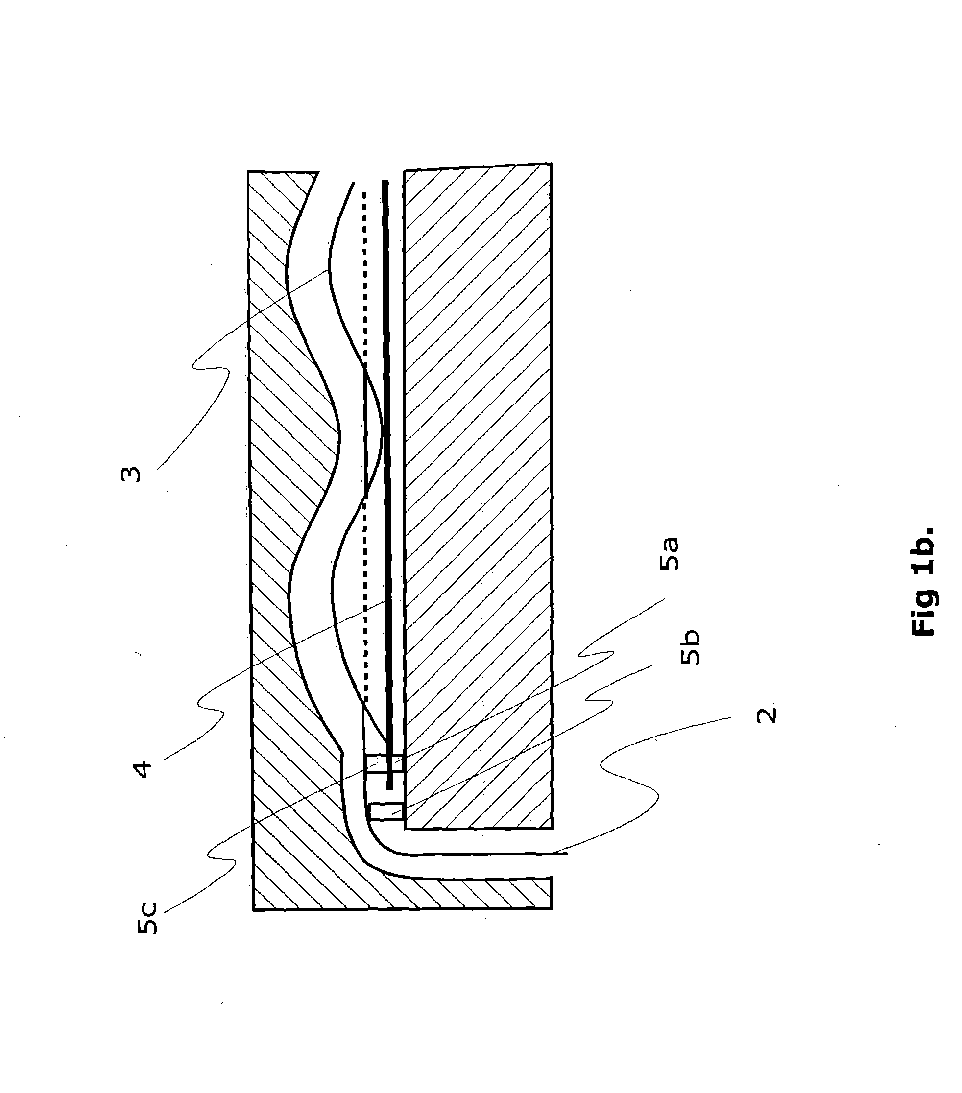
[0011] It is an object of the invention to provide a electromechanical structure comprising a user interface and a printed wired board, which structure is advantages in terms of manufacturing and offers freedom to the layout design of the printed wired board, the user interface as well as the appearance of the device itself. It is also an object of the invention to provide a electromechanical structure that is compact and facilitates the customizability and upgradability with a new electronic functionality without any need for modifications to the main electronics of the device.
[0038] As a consequence of the invention numerous advantages are achieved. The layout design of the user interface and the printed wired board is freed from the characteristics and design of the main electronic device and the standardized engine PWB layout. In portable electronics there is a drive to standardize the engine PWB, but at the same time there is a drive to expand the types of user interfaces of the portable devices. A great degree of freedom is given to design of cover parts and exchangeable outer covers. The manufacturing technologies and processes according to the invention also allow new electronic functions to be produced in the cover part. The location, number and size of electronic functional elements become completely independent of the engine PWB layout. Minituarisation is made possible because large areas of the engine PWB surface space are left free, or the saved PWB surface is free for other use. Realization of watertight and hermetically sealed touch-controlled electronic devices become easier to produce because the manufacturing technology enables complete sealing of the electromechanical assembly and user interface when enfold into the plastic resin. The manufacturing process according to invention is affordable in price.

Problems solved by technology

This means that the keypad arrangement and the engine PWB layout is fixed to each other and it will be difficult to change the keypad layout without changing the engine PWB.
This kind of keypad arrangement limits a lot the freedom to design differentiated keypad layouts to exchangeable cover parts of the portable electronic devices.

Method used


Image

  • Integrated electromechanical arrangement and method of production
  • Integrated electromechanical arrangement and method of production
  • Integrated electromechanical arrangement and method of production

Examples


Embodiment Construction

[0049] An electromechanical assembly for an electronic device comprises both electrical and mechanical function components which will be part of the electronic device. Typically an electromechanical assembly is an input / output device to relay information from user to the electronic unit of the electronic device, and vice versa. The input / output device is activated by pressing, touching, blowing or acting other physical manner to the user interface of the input / output device. In this description the term assembly is used to describe that the system comprises both electronic and mechanical components, e.g. a keypad assembly comprises electronic components such as conductors, resistors, detectors, leds etc. on a printed wired board and mechanical components such as keydomes on a printed wired board. In portable electronic devices multi-layer foils made of flexible conductive material are commonly used as a platform for an electronic circuitry instead of printed wired boards. Thus, in t...


PUM

PropertyMeasurementUnit
electricallyaaaaaaaaaa
conductiveaaaaaaaaaa
non-conductiveaaaaaaaaaa

Abstract

It is an object of the invention to provide a electromechanical structure comprising an input device and a printed wired board (3, 4), which structure is advantages in terms of manufacturing and offers freedom to the layout design of the printed wired board, the user interface as well as the appearance of the device itself. It is also an object of the invention to provide a electromechanical structure that is compact and facilitates the customizability and upgradability with a new electronic functionality without any need for modifications to the main electronics of the device. This is achieved by integrating the electromechanical assembly with the mechanical cover part of the electronic device by using an injection moulding process to compose an integrated combination (113) which is detachable from the electronic device. More precisely the objects of the invention are achieved by combining the injection mould technologies with the printing of electronic wired boards.

Description

TECHNICAL FIELD OF THE INVENTION [0001] The present invention relates generally to the electromechanical structures of portable electronic devices, electronic circuits, printed wired boards, electronic components and encapsulation. Especially the invention concerns the integration of electromechanical keypad arrangements and mechanical parts of an electronic device. BACKGROUND OF THE INVENTION [0002] An input device is an important part of many portable electronic devices and it is used to control operation and input information to the electronic device. In portable electronic devices such as computers, communication devices, measuring devices and similar devices the most common input devices used are keypads, keyboards and touch panels consisting of individually pressable or touchable numeric or alphanumeric, function and control keys. To activate these kind of input devices a user must press or touch a certain key or a certain touch point to accomplish a desired operation. [0003] ...

Claims


Application Information

Patent Timeline
Patent Type & Authority Applications(United States)
IPC IPC(8): B29C45/14G06F3/02G06F3/033G06F3/041H01H13/81H01H13/86H05K1/18H05K3/00H05K3/40
CPCB29C45/14639H05K2203/1327G06F3/0202G06F3/03547G06F3/0414H01H13/81H01H13/86H01H2207/008H01H2207/02H01H2215/008H01H2219/002H01H2219/018H01H2219/028H01H2223/028H01H2229/047H01H2229/05H05K1/189H05K3/0058H05K3/4015B29C45/14688
Inventor NARHI, KATRITAKALA, ROOPENOUSIAINEN, JARIAHLGREN, PENTTITANSKANEN, PIA
Owner NOKIA TECHNOLOGLES OY
Learn More