Communication system, a communication method, and a communication apparatus

a communication system and communication method technology, applied in the field of communication systems and communication methods, can solve the problems of no protocol capable of coexistence of access points, difficult combination of carrier sense according to the ieee 802.11 standard and space division multiplexing with adaptive array antennas, etc., and achieve the effect of eliminating overhead, simple structure and low cos

Active Publication Date: 2005-01-06
REDWOOD TECHNOLOGIES LLC
View PDF12 Cites 102 Cited by
  • Summary
  • Abstract
  • Description
  • Claims
  • Application Information

AI Technical Summary

Benefits of technology

[0021] In this communication system according to the present invention, the first communication station transmits the request to send signal describing at least addresses of a plurality of the second communication stations that are desired to receive the data, and receive a plurality of clear to send signals transmitted from each of a plurality of the second communication stations. Thus, the first communication station can transmit data to a plurality of communication stations at the same time with the coexistence with communication stations operating in accordance with the conventional protocol, so that a communication capacity of the network can be extremely increased.
[0037] The communication apparatus of the present invention receives the request to send signal describing addresses of a plurality of communication station requested to receive the data and generates a clear to send signal in accordance with this, so that the data can be transmitted to a plurality of communication stations at the same time with the coexistence with communication stations operating according to the conventional protocol. Thus, the use of the communication apparatus for receiving data makes it possible to provide a setting up of a network having an extremely increased communication capacity.

Problems solved by technology

However in the wireless LAN, two techniques, namely, the carrier sense according to the IEEE 802.11 standard and the Space Division Multiplexing with the adaptive array antenna, are difficult to combine.
In addition, in the wireless LAN, there is no protocol capable of the coexistence of an access point having the adaptive array antenna under the environment where there are stations operating according to the conventional protocol.

Method used


Image

  • Communication system, a communication method, and a communication apparatus
  • Communication system, a communication method, and a communication apparatus
  • Communication system, a communication method, and a communication apparatus

Examples


first embodiment

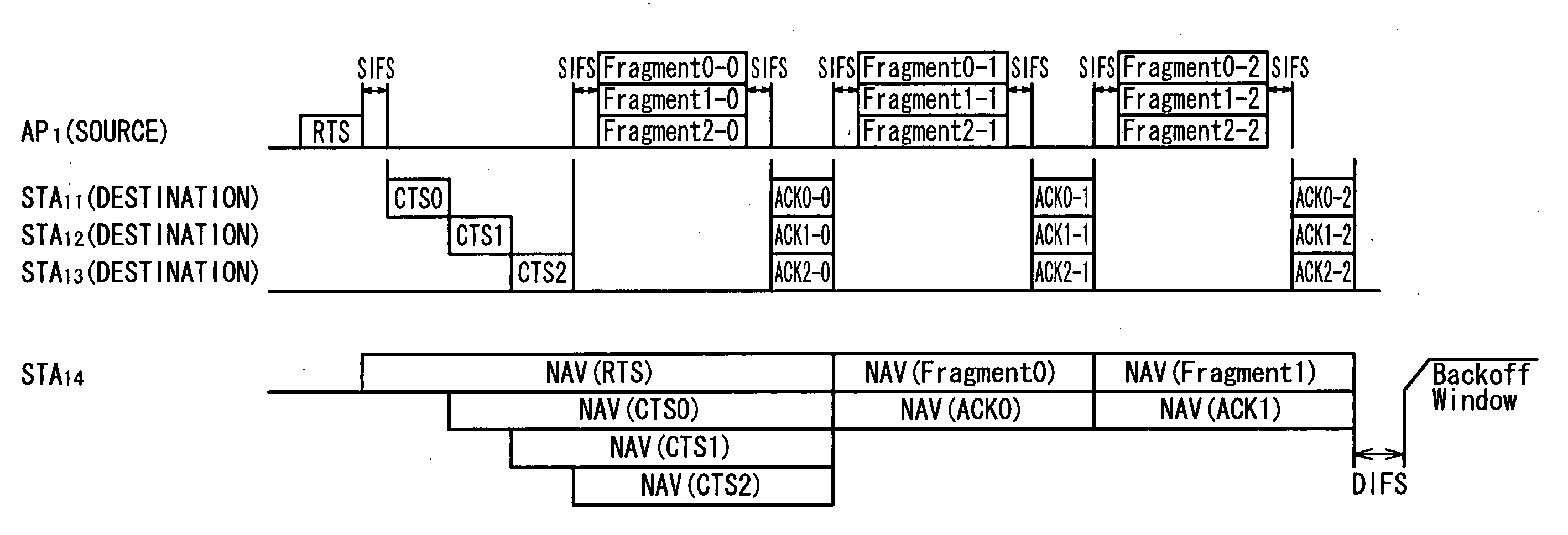
[0098] As mentioned above, in the communication system according to the present invention, a plurality of stations STA11, STA12, and STA13, that receive the RTS signal transmitted from the access point AP1 time-divisionally return the CTS signals, and the access point AP1 learns the weightings for the equipped adaptive array antenna to form the directivity. During this, at the first learning, the weightings for the adaptive array antenna are obtained by acquiring the transfer functions on the basis of the RANDPAT in a plurality of the time-divided CTS signals. At or after the second learning, the weightings for the adaptive array antenna is directly obtained on the basis of the RANDPAT in a plurality of ACK signals which are space division multiplexed. Thus, while the coexistence with the station operating according to the conventional protocol is possible, the space division multiplexing in the downlink transmission from the access point AP1 to the stations STA11, STA12, and STA13 ...

second embodiment

[0103] Then, in the communication system a new format is proposed in which the CTS signal is divided into the former half part and the latter half part, and the former half parts each describing at least the Duration are returned at the same time and the latter half parts each describing at least the RANDPAT are time-divisionally returned to solve such a problem. Specifically, the frame formats for the RTS signal and the CTS signals used in this communication system are proposed as shown in FIGS. 10A, 10B, 11A, and 11B.

[0104] The newly proposed RTS signal, as shown in FIGS. 10A and 10B, is generally divided into a former half part having the same structure as the conventional RTS signal and the newly added latter half part. More specifically, the former half part of the RTS signal includes, as shown in FIG. 10A, two octets of a Frame Control, two octets of a Duration, six octets of a Receiver Address RA and a Transmitter Address TA, and four octets of a Frame Check Sequence FCS. Th...

third embodiment

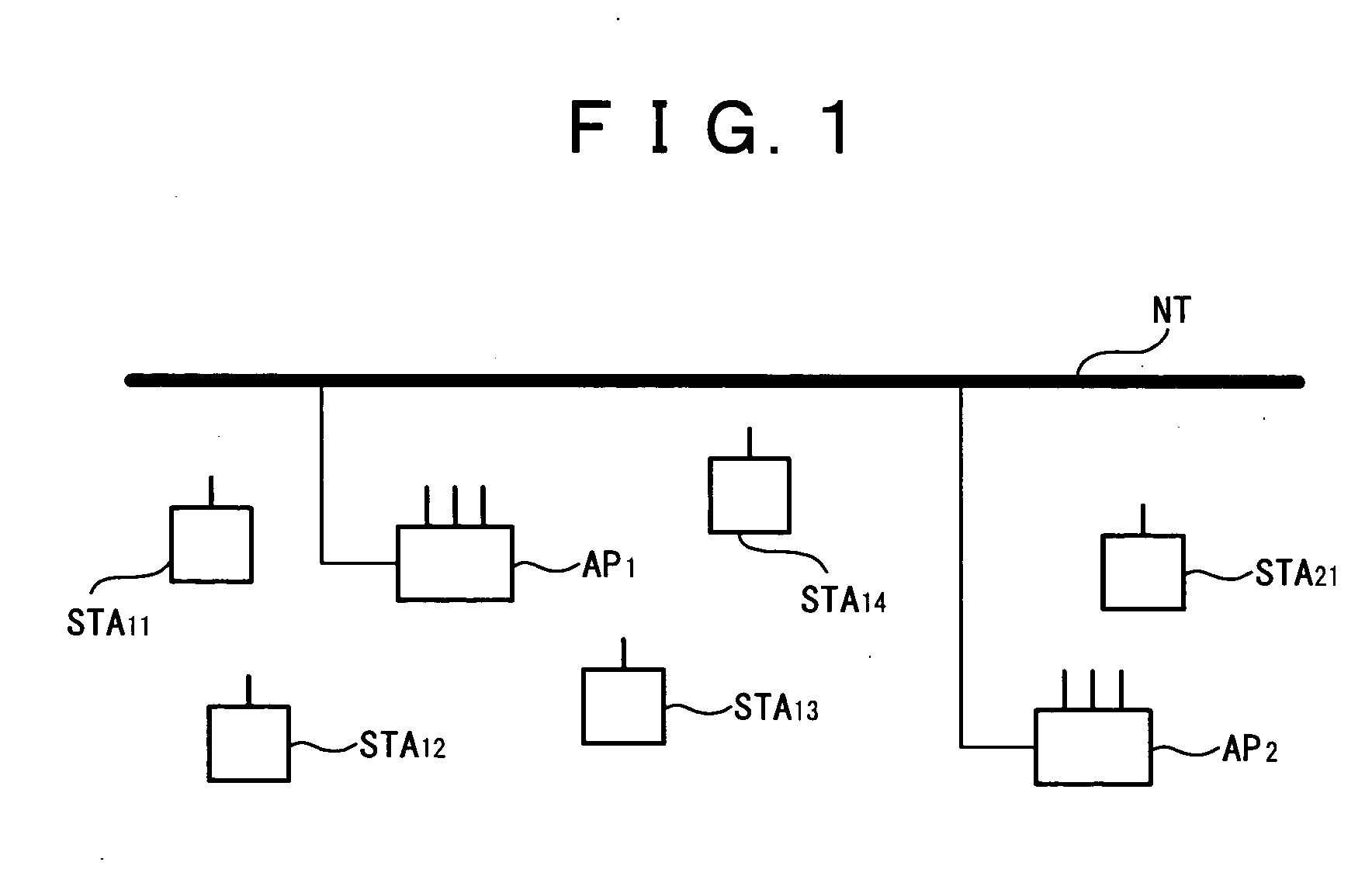
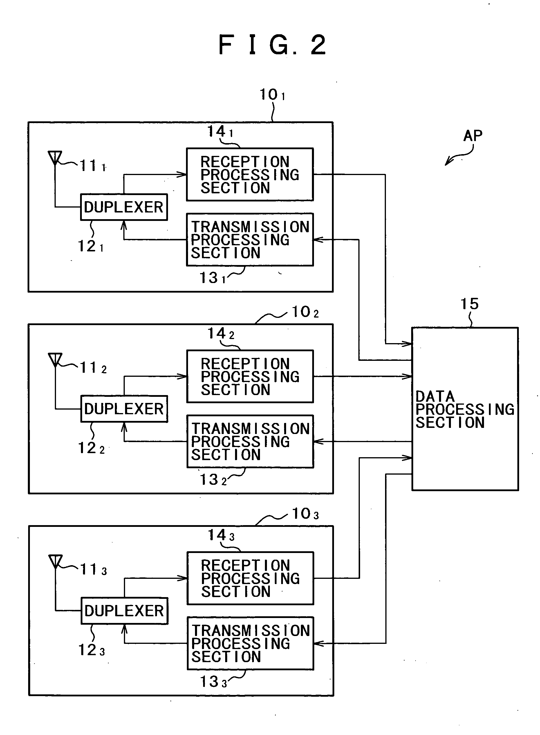
[0124] Here, the communication system is provided in the same network in structure as that shown in FIG. 1, and the access points and stations have the same structures as those shown in FIGS. 2 and 3, respectively. Further, the format of the RTS signal is the same as that shown in FIGS. 10A and 10B and the format of the CTS signal is the same as that shown in FIGS. 11A and 11B. Thus, the corresponding parts to the first and embodiments are designated with the same references and thus, the detailed descriptions are omitted.

[0125] In the communication system according to the third embodiment, returning the CTSadd signals at the same time in addition to the CTS 802.11 signals eliminates the overhead due to the time-divisional transmission in the communication systems according to the first and second embodiments.

[0126] More specifically, the RTS signals and the CTS signals transmitted and received in this communication system are the same as those shown in FIGS. 10A, 10B, 11A and 11B...


PUM


Abstract

A communication system for carrying out data communication among a plurality of communication stations is disclosed in which a first communication station for transmitting to other communication stations a Request To Send (RTS) signal for requesting a transmission upon the start of the data transmission; and a plurality of second communication stations transmitting to other communication stations a Clear To Send (CTS) signal for notifying the completion of preparing the reception, wherein the first communication station transmits the RTS signal describing at least each of addresses the second communication stations that are desired to receive the data, and receives a plurality of CTS signals transmitted from each of the second communication stations in order to increase communication capacity.

Description

CROSS REFERENCE TO RELATED APPLICATION [0001] This application claims priority from Japanese Priority Document No. 2003-123280, filed on Apr. 28, 2003 with the Japanese Patent Office, which document is hereby incorporated by reference. BACKGROUND OF THE INVENTION [0002] 1. Field of the Invention [0003] This invention relates to a communication system and a communication method for carrying out data communications among a plurality of communication stations, and in a communication apparatus used in these communication system and communication method, this invention particularly relates to a communication system, a communication method, and a communication apparatus suitable for applying to wireless LAN (Local Area Network). [0004] 2. Description of the Related Art [0005] Recently, for example, the near filed wireless communication techniques have been developed for wirelessly coupling various types of data processing terminals together, such as personal computers or portable data ter...

Claims


Application Information

Patent Timeline
Patent Type & Authority Applications(United States)
IPC IPC(8): H04B7/26H04L1/16H04L12/28H04W4/00H04W16/28H04W72/04H04W74/04H04W84/12H04W88/08
CPCH04W74/0816H04L1/1671
Inventor TAKANO, HIROAKI
Owner REDWOOD TECHNOLOGIES LLC
Why Eureka
Try Eureka