Spatial scalable compression

Inactive Publication Date: 2005-01-06
KONINKLIJKE PHILIPS ELECTRONICS NV
View PDF3 Cites 46 Cited by
  • Summary
  • Abstract
  • Description
  • Claims
  • Application Information

AI Technical Summary

Benefits of technology

[0008] It is an object of the invention to overcome at least part of the above-described deficiencies of the known spatial scalability schemes by providing a spatial sc

Problems solved by technology

Because of the massive amounts of data inherent in digital video, the transmission of full-motion, high-definition digital video signals is a significant problem in the development of high-definition television.
As a result, the amounts of raw digital inform

Method used


Image

  • Spatial scalable compression
  • Spatial scalable compression
  • Spatial scalable compression

Examples


Embodiment Construction

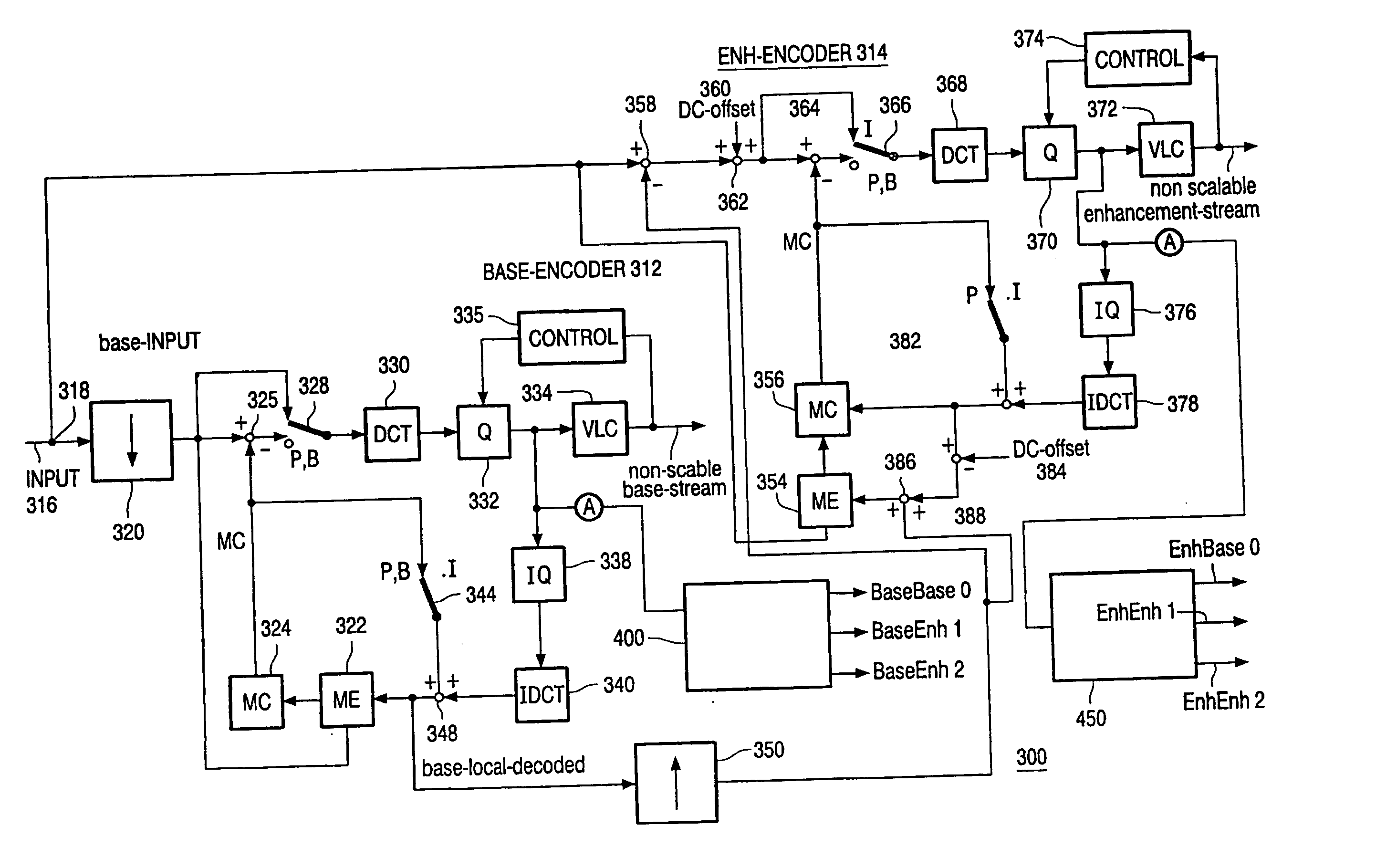
[0020]FIG. 3 is a schematic diagram of an encoder according to one embodiment of the invention. The depicted encoding system 300 accomplishes layered compression, whereby a portion of the channel is used for providing a plurality of lower resolution base layers and the remaining portion is used for transmitting a plurality of enhancement layers, whereby various base layers and base and enhancement layers can be combined to create video streams of differing quality levels. It will be understood by those skilled in the art that other encoding arrangements can also be used to create multilayered base and enhancement video streams and the invention is not limited thereto.

[0021] The encoder 300 comprises a base encoder 312 and an enhancement encoder 314. The base encoder is comprised of a low pass filter and downsampler 320, a motion estimator 322, a motion compensator 324, an orthogonal transform (e.g., Discrete Cosine Transform (DCT)) circuit 330, a quantizer 332, a variable length co...


PUM


Abstract

An apparatus for efficiently performing spatial scalable compression of an input video stream is disclosed. A base encoder encodes a base encoder stream. Modifying means modifies content of the base encoder stream to create a plurality of base streams. An enhancement encoder encodes an enhancement encoder stream. Modifying means modifies content of the enhancement encoder stream to create a plurality of enhancement streams.

Description

FIELD OF THE INVENTION [0001] The invention relates to a video encoder, and more particularly to a video encoder which uses spatial scalable compression schemes to produce a plurality of base streams and a plurality enhancement streams. BACKGROUND OF THE INVENTION [0002] Because of the massive amounts of data inherent in digital video, the transmission of full-motion, high-definition digital video signals is a significant problem in the development of high-definition television. More particularly, each digital image frame is a still image formed from an array of pixels according to the display resolution of a particular system. As a result, the amounts of raw digital information included in high resolution video sequences are massive. In order to reduce the amount of data that must be sent, compression schemes are used to compress the data. Various video compression standards or processes have been established, including, MPEG-2, MPEG-4, H.263 and H.264. [0003] Many applications are...

Claims


Application Information

Patent Timeline
IPC IPC(8): G06T9/00H03M7/36H04N1/41H04N7/26H04N7/30H04N7/32H04N7/46H04N7/50H04N19/593
CPCH04N19/172H04N19/198H04N19/61H04N19/12H04N19/124H04N19/132H04N19/137H04N19/152H04N19/187H04N19/192H04N19/33H04N19/517H04N19/59H04N19/577H04N19/196H04N19/44H04N19/625
Inventor BRULS, WILHELMUS HENDRIKUS ALFONSUSKLEIN GUNNEWIEK, REINIER BERNARDUS MARIA
Owner KONINKLIJKE PHILIPS ELECTRONICS NV
Why Eureka
Try Eureka