Camera based position recognition for a road vehicle

a technology for road vehicles and position recognition, applied in vehicular safety arrangements, pedestrian/occupant safety arrangements, instruments, etc., can solve the problems of poor reliability and affecting the use of vehicle guidance guidelines in dynamic street traffic scenarios. achieve the effect of high reliability

Inactive Publication Date: 2005-01-06
DAIMLER AG
View PDF5 Cites 106 Cited by
  • Summary
  • Abstract
  • Description
  • Claims
  • Application Information

AI Technical Summary

Benefits of technology

In the novel camera based position recognition system for a road vehicle, the environment in the direction of travel of the vehicle is acquired by a camera. Using the acquired image data, the position of the vehicle in its environment is determined with regard to an optical signature identified in the obtained image data. For determining the position, use is made of the knowledge of the relationship between the environment coordinate system of the optical signature and that of the camera coordinate system. In simplified manner, the position determination occurs with regard to the optical signature on the basis of a template matching imposed on the image data. For this, a template or an optical signature recorded in memory is superimposed on the optical signature identified in the image data in the environment of the vehicle (templa

Problems solved by technology

The detection of the light intensity profile by the line camera is however very susceptible to dirt on the optical signatures or frictional wearing away of the optical signatures provided on the roadway.
Further, the use of guidelines for guiding a vehicle is not suited for employment in a dynamic street traffic scenario.
Further yet, the optical signature is not detected until the vehicle has

Method used


Image

  • Camera based position recognition for a road vehicle
  • Camera based position recognition for a road vehicle
  • Camera based position recognition for a road vehicle

Examples


Embodiment Construction

In particularly preferred manner, an at least semi-autonomous vehicle guidance is initiated based upon the knowledge or acquisition of the position of the vehicle with regard to the optical signature. In the framework of this vehicle guidance, the vehicle is brought to a halt, for example at a predetermined position relative to the optical signature. It is also conceivable, beginning at a position defined in relation to the optical signature, for example in the case of directional arrows on the roadway, to orient the vehicle in a defined manner on the roadway, or, in the case of the recognition of a stop line associated with a traffic signal, to bring the vehicle to a halt using an ideal braking sequence in the case of red traffic signal.

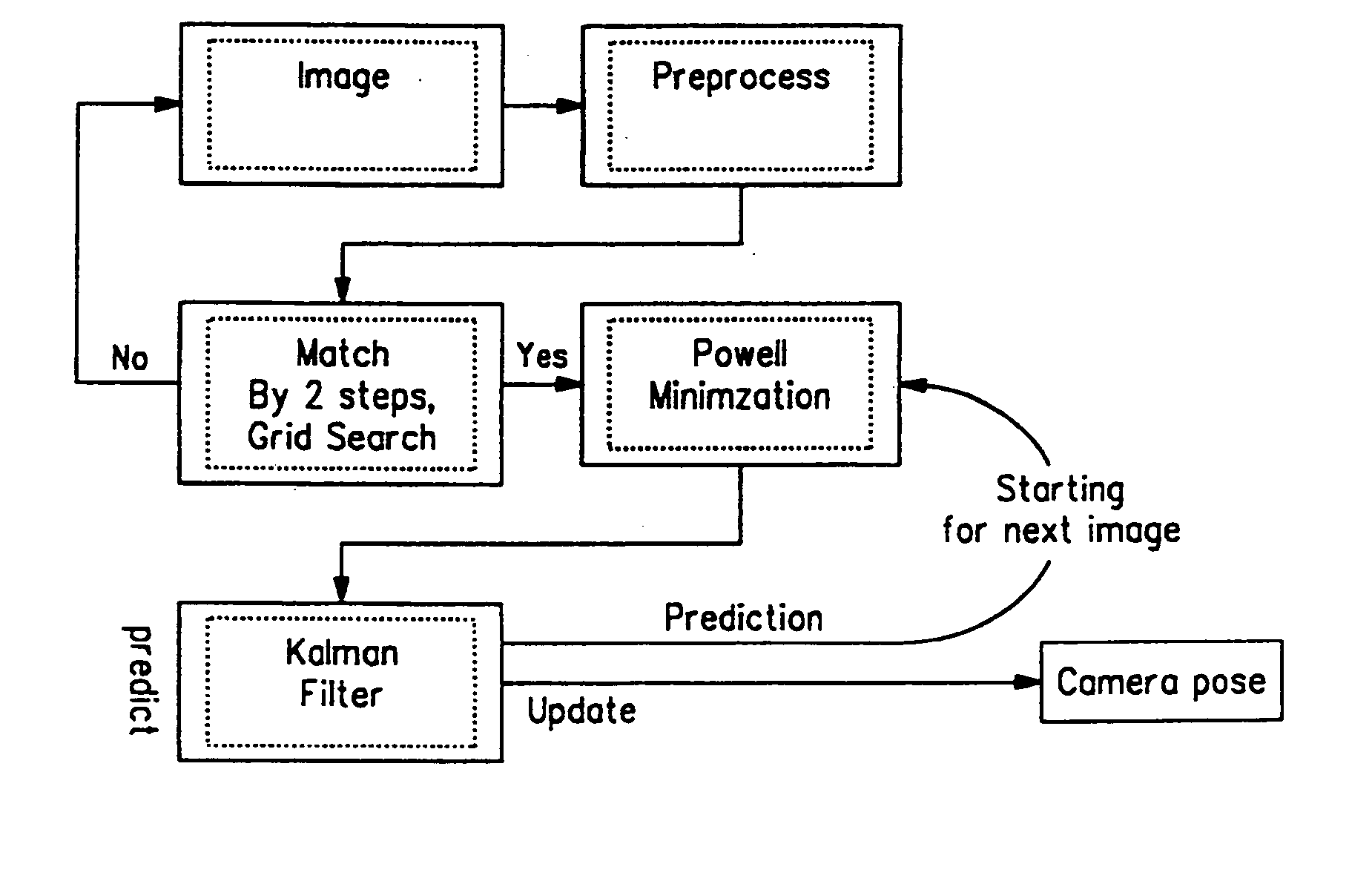
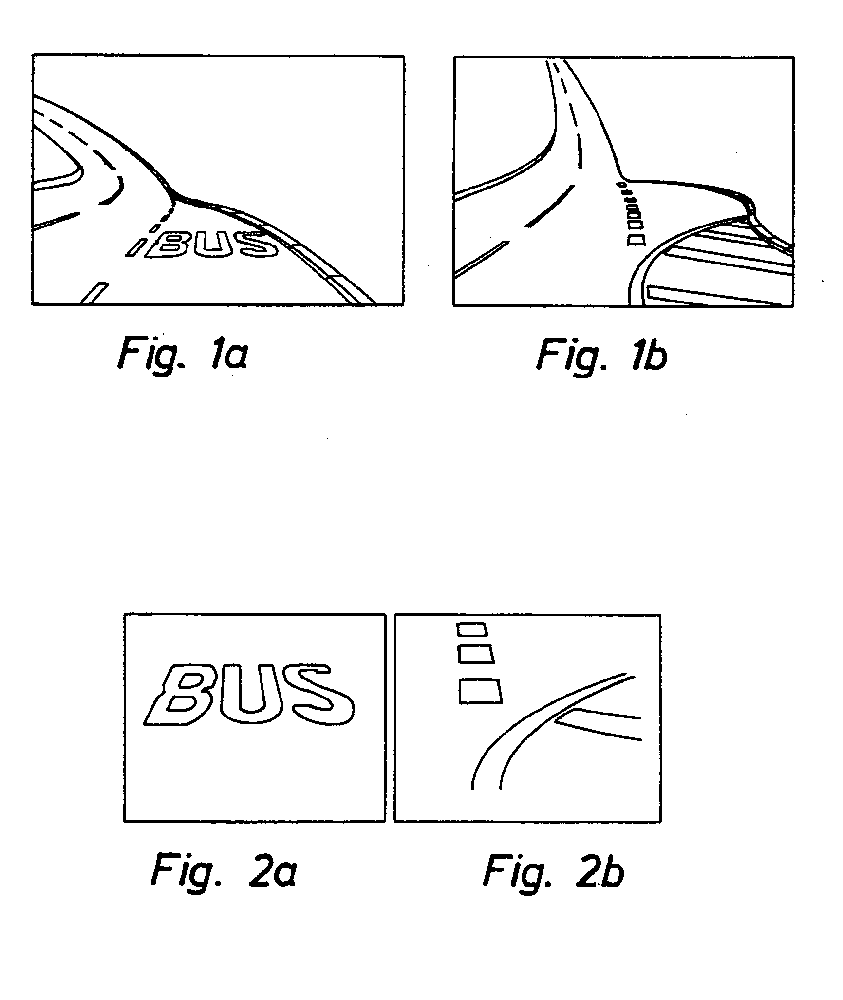
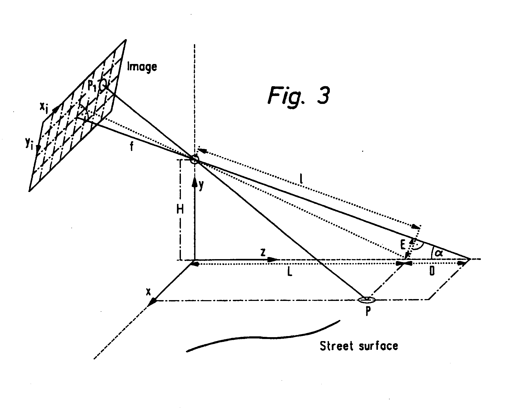
In particularly useful manner the invention can be designed such that template matching occurs in a three dimensional coordinate space. Thereby it becomes possible not to limit the optical signatures, on the basis of which the position of the roa...


PUM


Abstract

A camera based position recognition system for a road vehicle. The environment in the direction of travel of the vehicle is acquired by a camera. Using the acquired image data, the position of the vehicle in its environment is determined with regard to an optical signature identified in the obtained image data. For determining the position of the vehicle, use is made of the knowledge of the relationship between the environment coordinate system of the optical signature and that of the camera coordinate system. In simplified manner, position determination occurs with regard to the optical signature on the basis of a template matching imposed on the image data. For this, a template or an optical signature recorded in memory is superimposed on the optical signature identified in the image data in the environment of the vehicle (template matching). From the parameters of this template matching (for example linear compression and rotation parameters) recognizing the existing coordinate system, the position of the vehicle relative to the optical signature can be directly deduced.

Description

BACKGROUND OF THE INVENTION 1. Field of Invention The invention concerns a device suitable for camera based position recognition in a road vehicle and a process suited for operation of such a device according to the precharactering portion of Patent Claims 1 and 13. 2. Related Art of the Invention In modern vehicles, in order to further increase the operating comfort of the road vehicle and to reduce the load on the vehicle operator, use has increasingly been made of autonomous or semi-autonomous functions. Thus, for example, with the aid of a system for the intelligent vehicle following the vehicle operator is assisted in maintaining spacing from the preceding vehicle, or with the aid of a camera-based traffic sign recognition system the vehicle operator is better able to concentrate, particularly in the inner city, on pedestrians and vehicles located on or near the street. In many every-day situations it is the task of a vehicle operator to guide his vehicle along a particula...

Claims


Application Information

Patent Timeline
IPC IPC(8): B60R1/00B60R21/00G06T1/00G06T7/00G06T7/60G06V10/44G08G1/123G08G1/16H04N7/18
CPCB60R1/00G06K9/4604G06K9/00798G06T7/0044G08G1/123G06K2209/23G06T7/74G06V20/588G06V10/44G06V2201/08
Inventor FRANKE, UWEHAHN, STEFAN
Owner DAIMLER AG
Why Eureka
Try Eureka