Predistortion circuit for a transmit system

a technology of pre-distortion circuit and transmit system, which is applied in the direction of transmission monitoring, baseband system details, simultaneous amplitude and angle demodulation, etc., can solve the problems of distortion, the process of input signal also introduces, and the chireix architecture has fallen out of favor

Active Publication Date: 2005-01-06
ZARBANA DIGITAL FUND
View PDF35 Cites 109 Cited by
  • Summary
  • Abstract
  • Description
  • Claims
  • Application Information

AI Technical Summary

Problems solved by technology

Named after Henry Chireix who first proposed such an architecture in the 1930s, the Chireix architecture has fallen out of favor due to its seemingly inherent limitations.
While the Chireix architecture provides some advantages, the process which the input signal undergoes also introduces some drawbacks.
Specifically, distortions are introduced into the signal by the components in the Chireix based amplifier / modulator system.

Method used


Image

  • Predistortion circuit for a transmit system
  • Predistortion circuit for a transmit system
  • Predistortion circuit for a transmit system

Examples


Embodiment Construction

For clarity, the following terms are to be used with the following definitions: AM (amplitude modulation) refers to the AM of an RF (radio frequency) signal and is equal to the magnitude of the RF signal's complex base band equivalent PM (phase modulation) refers to the PM of an RF signal and is equal to the phase of the RF signal's complex base band equivalent.

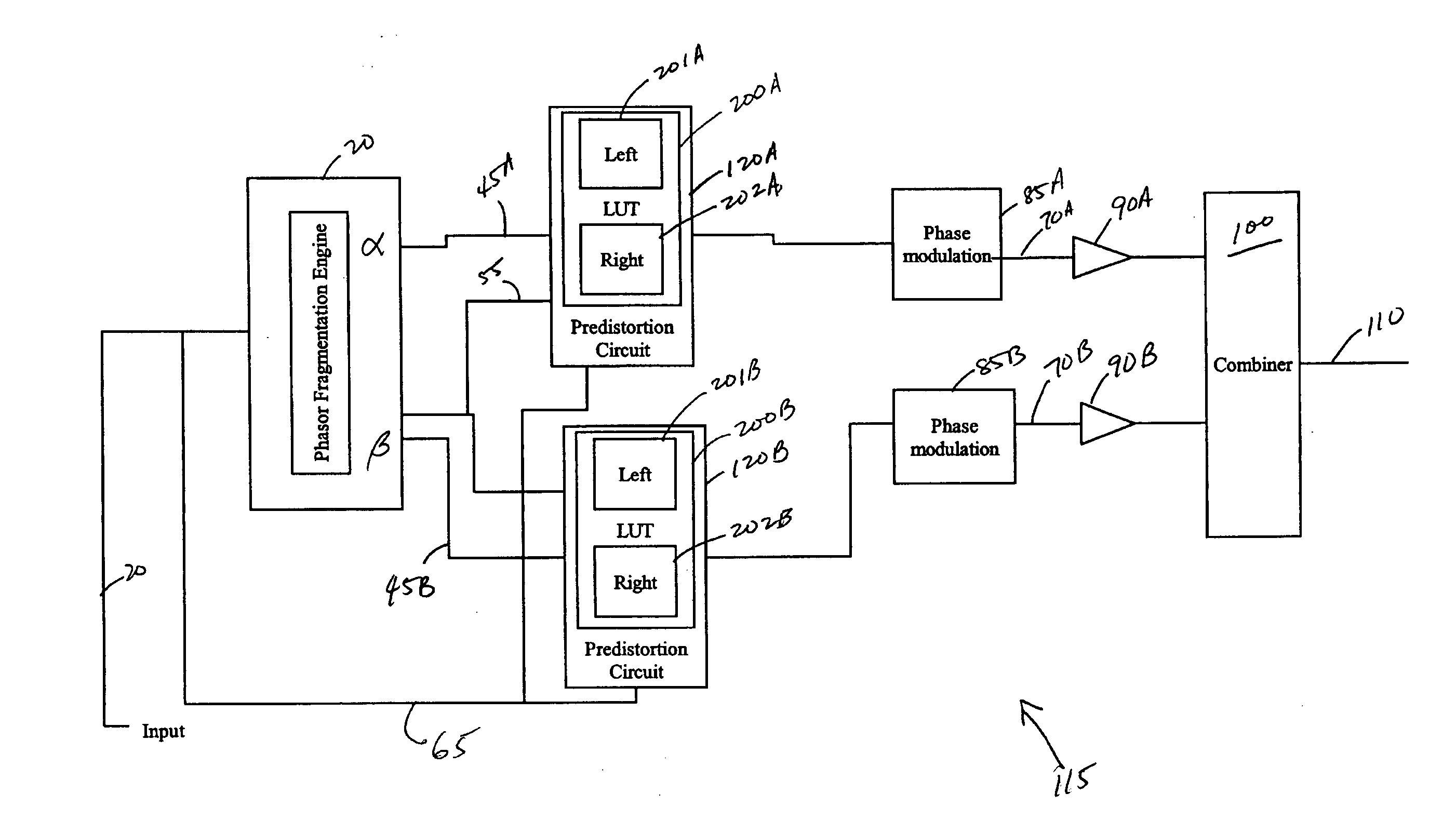
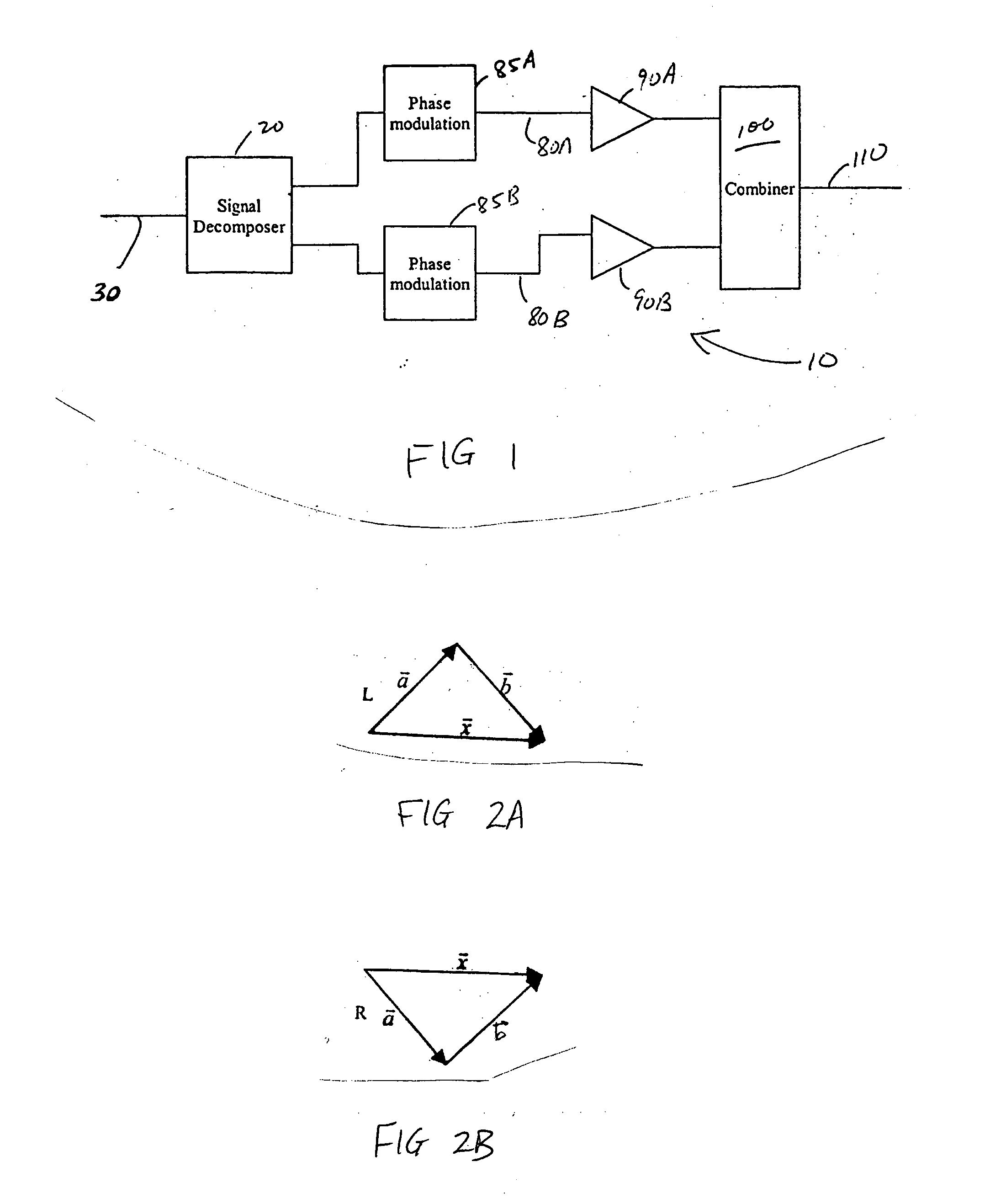
Referring to FIG. 1, a block diagram of a Chireix architecture amplifier subsystem 10 is illustrated. A signal decomposer 20 receives an input complex baseband signal 30. Phase modulated RF signals 80A, 80B are produced after the decomposed output of the decomposer 20 are phase modulated by phase modulation circuitry 85A, 85B. These phase modulated signals 80A, 80B are received by power amplifiers 90A, 90B. The phase modulated signals are thus amplified by the power amplifiers 90A, 90B and are received by a signal combiner 100. The system output signal 110 (an RF signal corresponding to the input baseband signal 30) is out...


PUM


Abstract

Systems and methods related to amplifier systems which use a predistortion subsystem to compensate for expected distortions in the system output signal. A signal processing subsystem receives an input signal and decomposes the input signal into multiple components. Each signal component is received by a predistortion subsystem which applies a predistortion modification to the component. The predistortion modification may be a phase modification, a magnitude modification, or a combination of both and is applied by adjusting the phase of the fragment. The predistorted component is then separately processed by the signal processing subsystem. The processing may take the form of phase modulation and amplification. The phase modulated and amplified components are then recombined to arrive at an amplitude and phase modulated and amplified output signal. The predistortion modification is applied to the components to compensate for distortions introduced in the signal by the signal processing subsystem.

Description

FIELD OF THE INVENTION The present invention relates generally to power amplification systems and is specifically applicable but not limited to power amplification systems using a Chireix architecture. BACKGROUND OF THE INVENTION The recent revolution in communications has caused a renewed focus on wireless technology based products. Mobile telephones, handheld computers, and other devices now seamlessly communicate using wireless technology. One component that forms the core of such technology is the amplifier. Wireless devices require high efficiency amplifiers to not only extend the range of their coverage but also to conserve the limited battery power that such devices carry. One possible architecture which may be used for such a power amplifier is called a Chireix architecture. Named after Henry Chireix who first proposed such an architecture in the 1930s, the Chireix architecture has fallen out of favor due to its seemingly inherent limitations. However, it has recently bee...

Claims


Application Information

Patent Timeline
Patent Type & Authority Applications(United States)
IPC IPC(8): H03F1/32H04B17/40H04L25/03
CPCH03F1/3247H04L25/03343H03F2201/3233H04M1/00
Inventor SAED, ARYAN
Owner ZARBANA DIGITAL FUND
Why Eureka
Try Eureka