Friction transmission belt

a transmission belt and friction technology, applied in the direction of driving belts, mechanical equipment, ropes and cables for vehicles/pulleys, etc., can solve the problems of noise generation, and achieve the effect of effectively suppressing belt deviation, and reducing the effect of correcting belt deviation

Inactive Publication Date: 2005-01-06
BANDO CHEM IND LTD
View PDF4 Cites 23 Cited by
  • Summary
  • Abstract
  • Description
  • Claims
  • Application Information

AI Technical Summary

Benefits of technology

[0011] According to the above-described embodiment, the belt has a tendency to run toward the direction of orientation of the short fibers in the short fiber-containing rubber, and thus side tracking of the belt tends to occur when the belt runs; therefore, the side tracking of the belt can offset and correct the belt deviation caused by external factors.
[0012] In the present invention, the direction of orientation of the short fibers in the short fiber-containing rubber preferably forms an angle of not less than 10° nor more than 45° with respect to the widthwise direction of the belt. This is because such an embodiment can effectively suppress belt deviation. That is, if this angle is smaller than 10°, the effect of correcting belt deviation might be lessened, and if this angle is greater than 45°, the tendency of the belt itself to cause side tracking is increased such that the effect of correcting belt deviation might be excessively heightened. From this viewpoint, as described in the aftermentioned embodiments, this angle is more preferably not less than 10° nor more than 30°.
[0013] Although an improvement in a cord embedded in the frictional forced power transmission belt can also forcibly provide the belt with a tendency to cause side tracking, the strength and elongation characteristic of the belt, for example, are considerably affected if the number of twist for the cord is optimized. Furthermore, if the spiral pitches of the cord provided spirally within the belt are constant, the spiral angle varies depending on the length of the belt; therefore, respective cord materials have to be prepared for various belts in order to provide each of the various belts with a certain tendency to cause side tracking, which increases the cost accordingly. To the contrary, according to the present invention, it is sufficient to prepare a single short fiber-containing rubber and to change the setting of the direction in which warp yarns in a cord fabric are extended, or the direction of orientation of the short fibers in the short fiber-containing unvulcanized rubber for each of the various belts, and therefore, the necessity of preparation of respective materials as in the improvement of the cord is obviated, thus suppressing a cost increase accordingly.

Problems solved by technology

Then, if the span length of the belt is shortened as described above, this belt deviation increases an alignment angle formed by the belt-running direction and the direction perpendicular to a pulley axis, thus causing the problem that noise is produced.

Method used


Image

  • Friction transmission belt
  • Friction transmission belt
  • Friction transmission belt

Examples


example 1

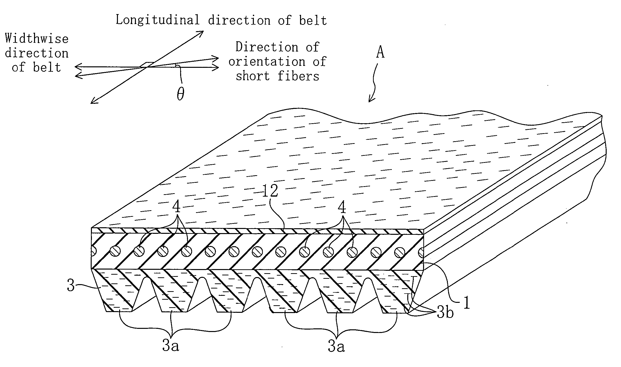
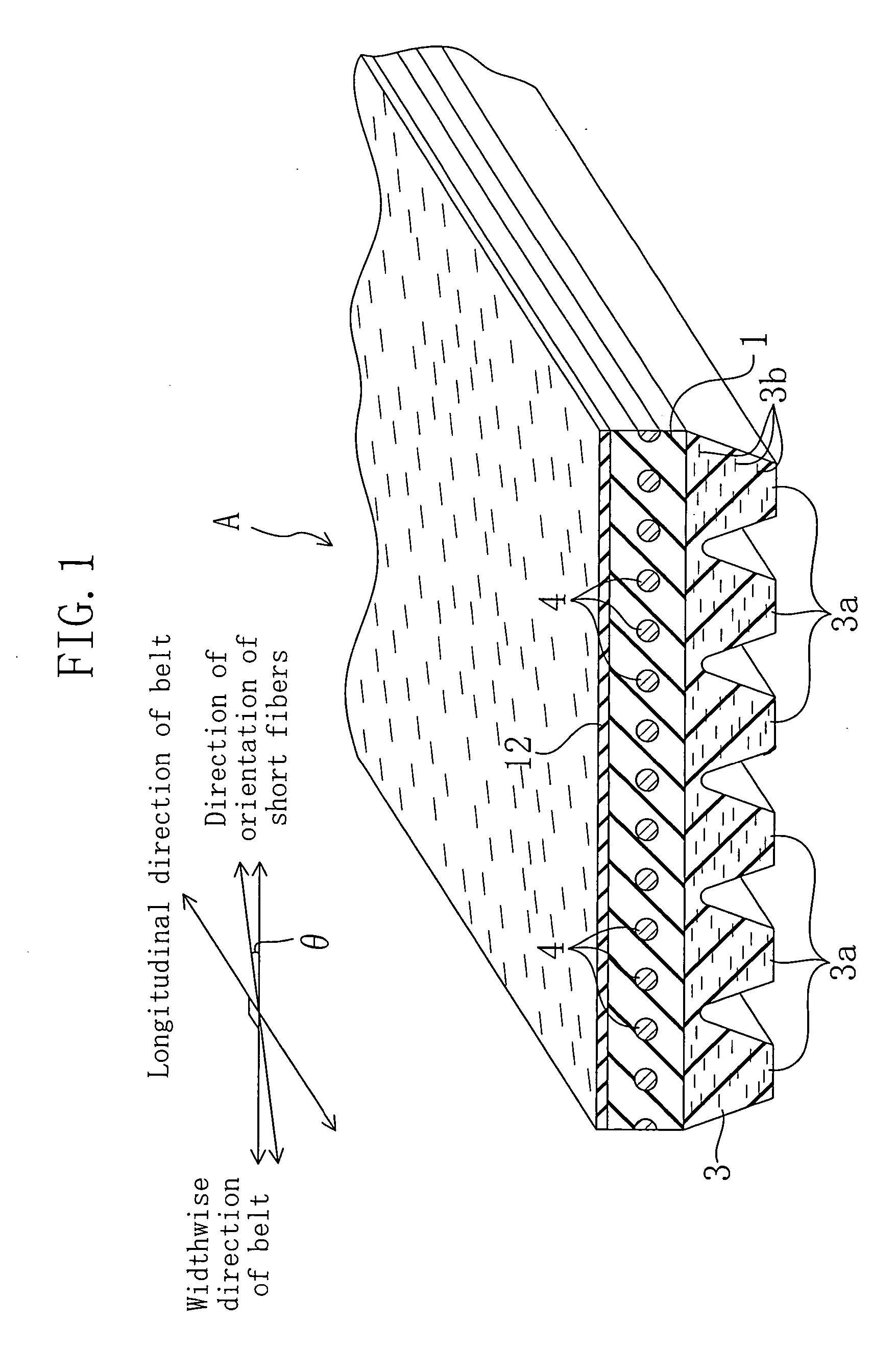
[0048] A V-ribbed belt according to Example 1 is provided at its back face with a plain weave reinforcement fabric so that an angle é that the direction, in which the bisector of intersecting angles of warp and weft yarns orthogonal to each other is extended, forms with respect to the belt widthwise direction is 0°, i.e., so that the direction of the bisector of the intersecting angles corresponds to the belt widthwise direction. The V-ribbed belt according to Example 1 does not have a tendency to cause side tracking in the belt widthwise direction. It should be noted that the number of ribs is three, and the length of the belt is 900 mm.

example 2

[0049] A V-ribbed belt according to Example 2 is formed in the same way as in Example 1, except the belt back face is provided with a plain weave reinforcement fabric so that an angle é that the direction, in which the bisector of intersecting angles of warp and weft yarns orthogonal to each other is extended, forms with respect to the belt widthwise direction is −10°. The V-ribbed belt according to Example 2 has a tendency to cause side tracking in the direction of the bisector of the intersecting angles of the warp and weft yarns.

example 3

[0050] A V-ribbed belt according to Example 3 is provided at its back face with a short fiber-containing back face rubber layer so that an angle é that the direction of orientation of short fibers forms with respect to the belt widthwise direction is 0°, i.e., so that the direction of orientation of the short fibers corresponds to the belt widthwise direction. The V-ribbed belt according to Example 3 does not have a tendency to cause side tracking in the belt widthwise direction. It should be noted that the number of ribs is three, and the belt length is 900 mm.


PUM

PropertyMeasurementUnit
angleaaaaaaaaaa
angleaaaaaaaaaa
angleaaaaaaaaaa

Abstract

In a frictional forced power transmission belt A whose back face is reinforced with a short fiber-containing rubber (12) into which short fibers oriented in a single direction are mixed, the short fiber-containing rubber (12) is provided integrally with the back face of the belt so that the direction of orientation of the short fibers forms an angle with respect to the widthwise direction of the belt.

Description

CROSS REFERENCE TO RELATED APPLICATIONS [0001] This application is a Section 371 of International Patent Application No. PCT / JP03 / 12180, filed Sep. 24, 2003, the disclosure of which is incorporated herein by reference.TECHNICAL FIELD [0002] The present invention relates to frictional forced power transmission belts. BACKGROUND ART [0003] In automobiles, V-ribbed belts are widely used to drive accessories such as fans, air conditioners, alternators and power steering. [0004] Japanese Unexamined Patent Publication No. 10-9344 discloses a related V-ribbed belt in which a plain weave fabric made of cotton fibers and synthetic fibers is stuck to the back face of the belt so that the center line of an angle between warp and weft yarns extends obliquely with respect to the longitudinal direction of the belt without performing any wide-angle process at all. This publication describes that such an arrangement provides, without performing any wide-angle process on the back face fabric, the re...

Claims


Application Information

Patent Timeline
Patent Type & Authority Applications(United States)
IPC IPC(8): F16G5/06F16G5/20
CPCF16G5/20F16G5/06
Inventor HAYASHI, TAKEHIRO
Owner BANDO CHEM IND LTD
Why Eureka
Try Eureka