

Turbine combustor endcover assembly
a technology of combustor and end cover, which is applied in the direction of machines/engines, mechanical equipment, light and heating equipment, etc., can solve the problem of needing to be machined ou
- Summary
- Abstract
- Description
- Claims
- Application Information
AI Technical Summary
Benefits of technology
Problems solved by technology
Method used
Image

Examples
Embodiment Construction
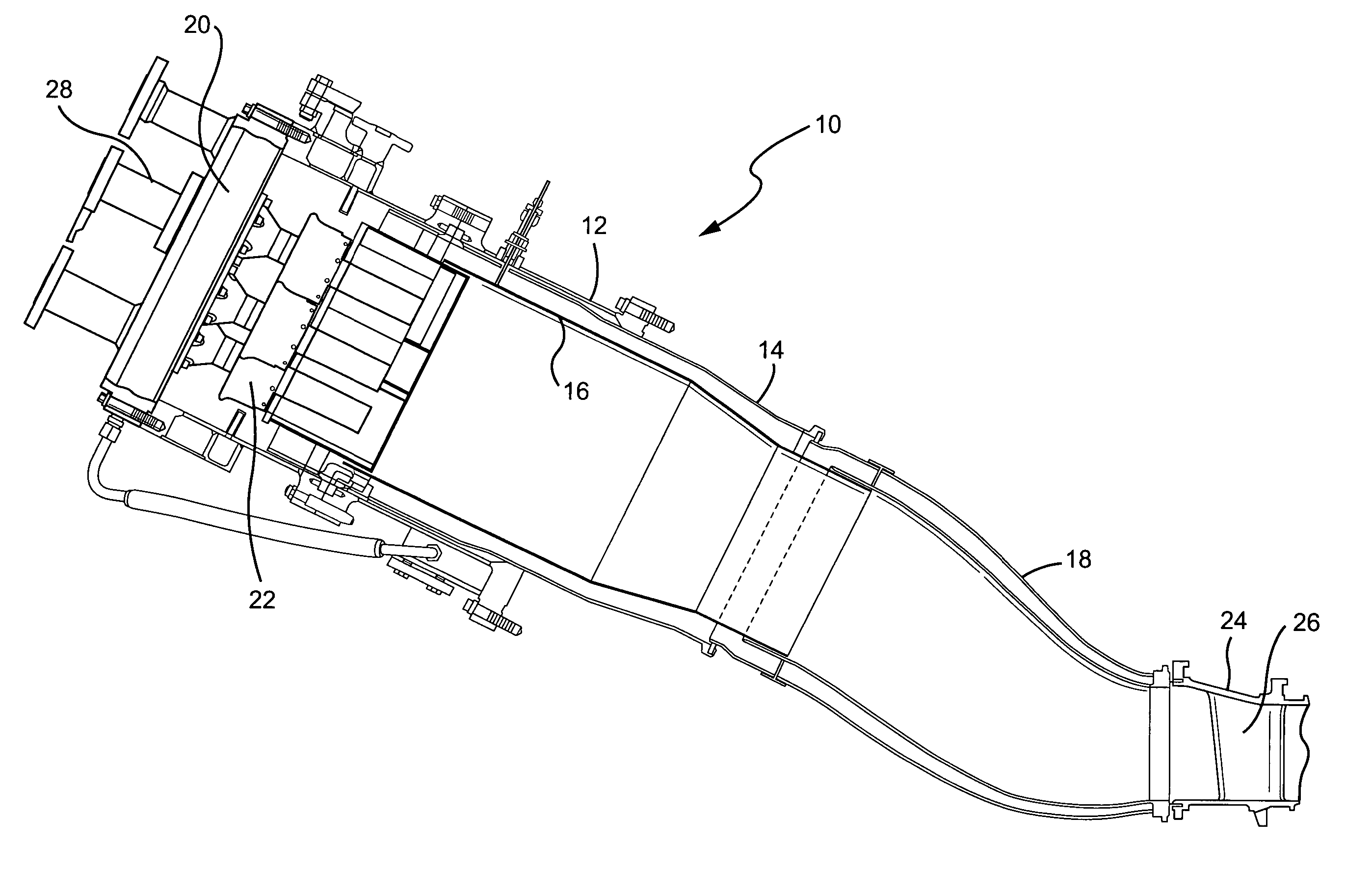
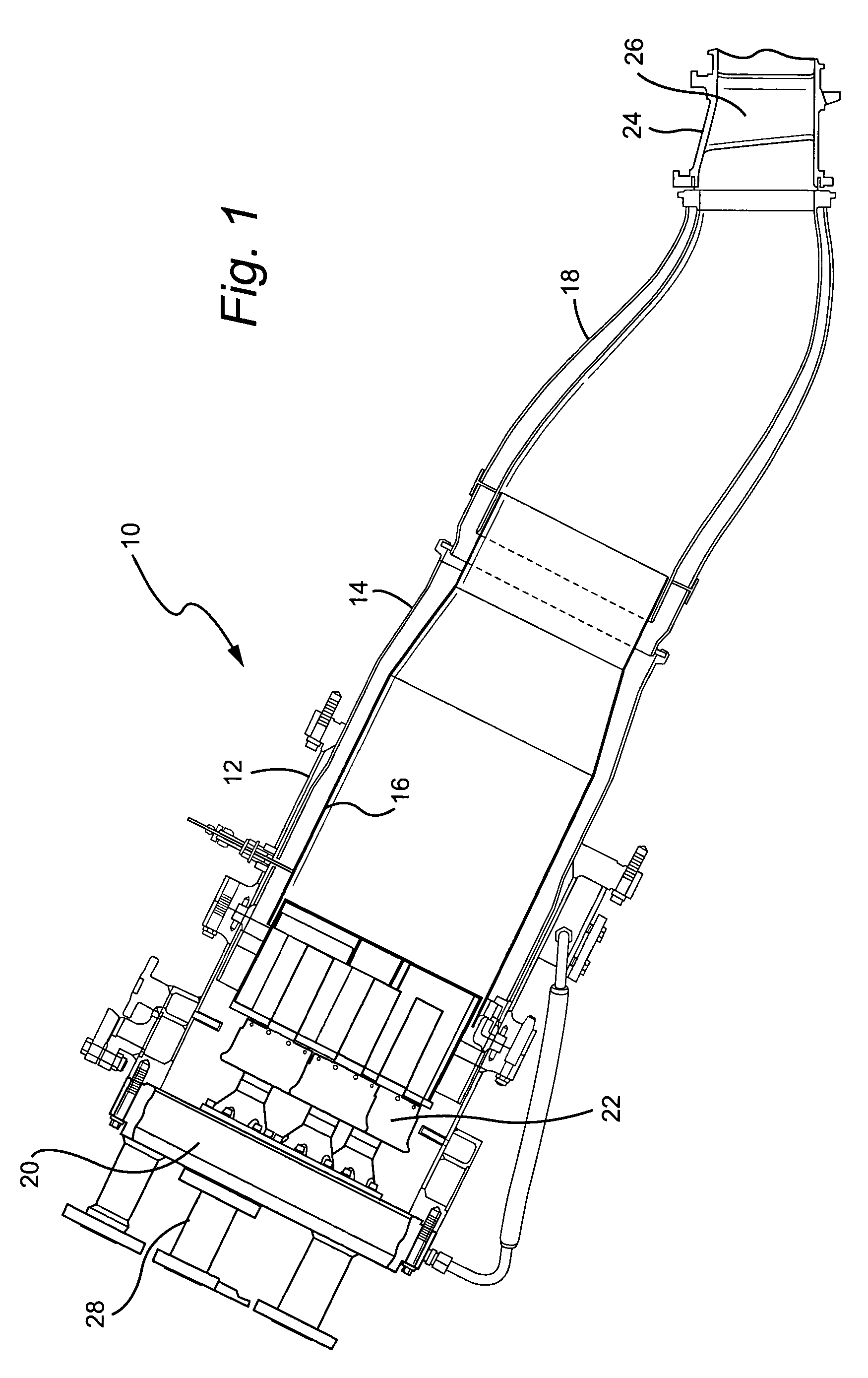
[0016] Referring now to the drawings, particularly to FIG. 1, there is illustrated a combustor employing an endcover assembly in accordance with a preferred embodiment of the present invention. The combustor, generally designated 10, includes an outer casing 12, a flow sleeve 14, a liner 16, a transition piece 18, an endcover 20 and a plurality of fuel nozzles 22. As typical in combustors, the flow sleeve 14 distributes compressor discharge air to the combustor, while cooling the liner 16. The endcover 20 encloses the head of the combustor, supplies purge air and fuel to the fuel nozzles 22 and forces air into the head end of the liner by way of the fuel nozzle bodies. The liner 16 provides an enclosure for the combustion process, while the transition piece 18 guides the products of combustion into the turbine section 24, the first stator blade of which is illustrated at 26. External plumbing connections 28 are provided on the endcover assembly 20 for supplying air and fuel to the n...
PUM
 Abstract
Description
Claims
Application Information