

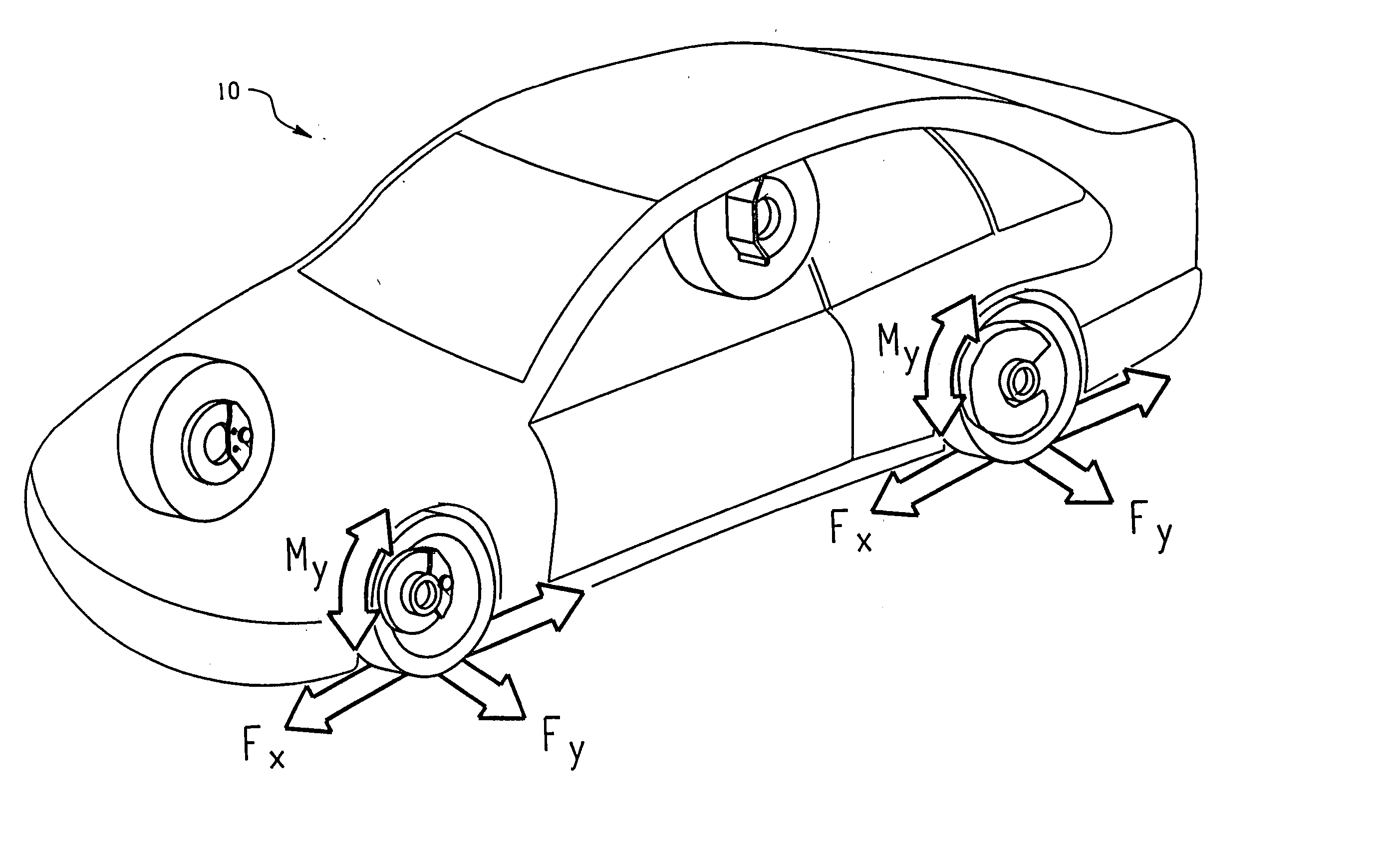
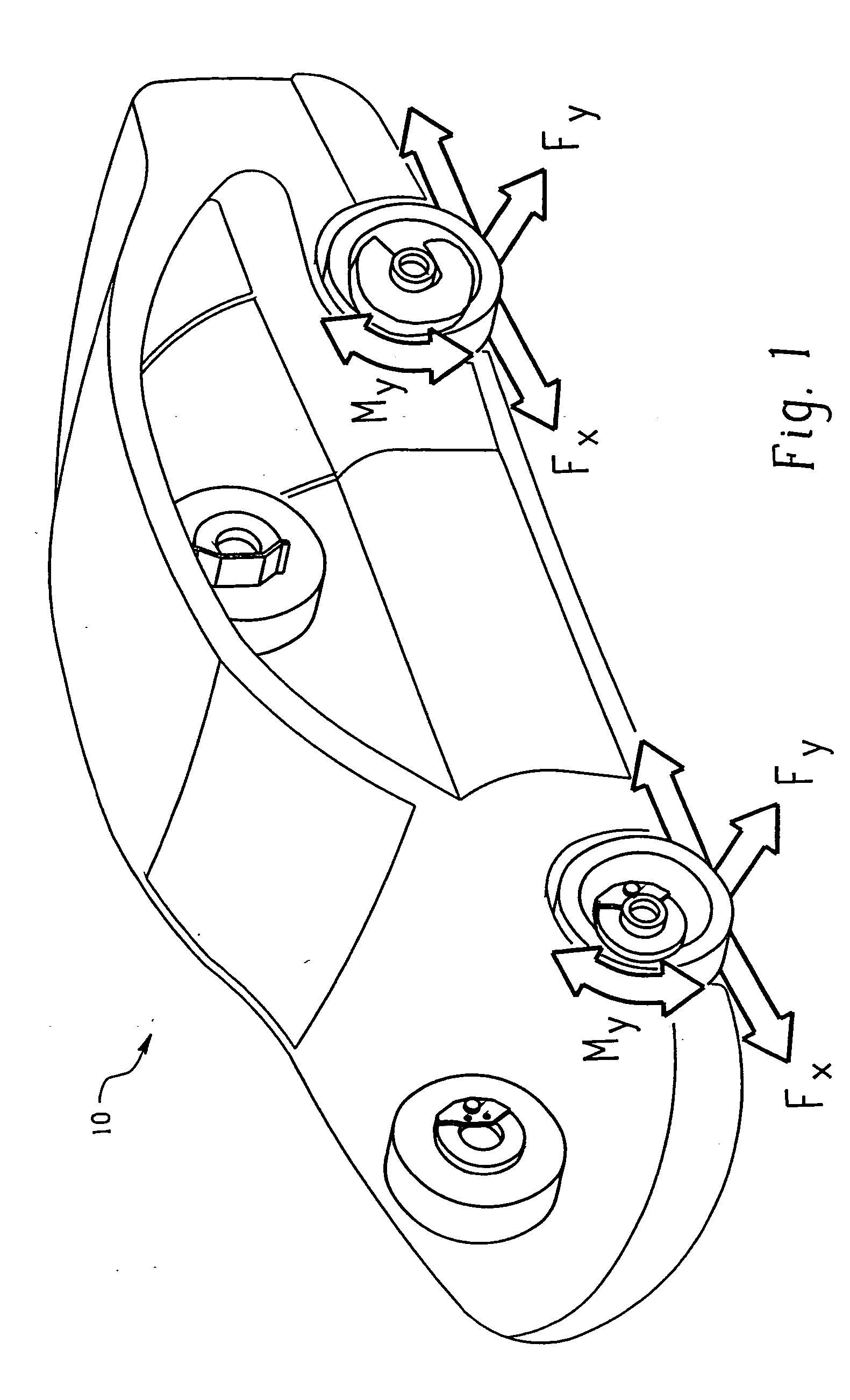
System and method for predicting tire forces using tire deformation sensors
a technology of deformation sensor and tire force, which is applied in the field of tire dynamics, can solve the problems of confounding the measurement of longitudinal torque using the swt sensor as originally envisioned, adversely and the force on the tire further affecting the calculation of driving torque or braking torqu
- Summary
- Abstract
- Description
- Claims
- Application Information
AI Technical Summary
Benefits of technology
Problems solved by technology
Method used
Image

Examples
example 1
Neural Network
First, a Conti Sport Contact, 245 / 40 R18 magnetic sidewall tire was prepared as generally described in U.S. Pat. No. 5,895,854 and copending U.S. patent application Ser. No. 09 / 347,757, with 200 phr (parts per hundred) of strontium ferrite powder embedded in the sidewall prior to curing. The embedded strontium ferrite was magnetized to magnetic saturation using 96 electromagnets providing 48 North poles alternating with 48 South poles.
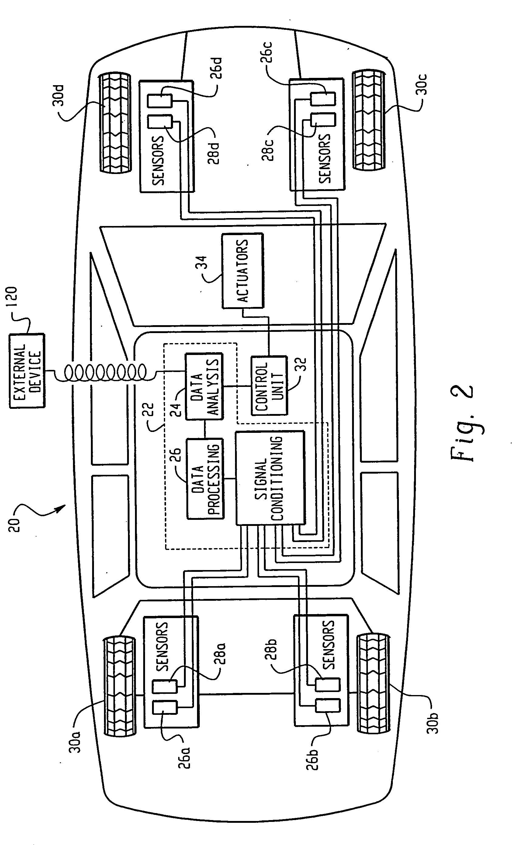
Next, the Conti Sport Contact tire was mounted on an MTS Model 860 tread wear machine (available from MTS Systems Corporation) as follows: The magnetic sidewall tire was mounted to a precision rim. Two pairs of SWT sensors (Philips KMZ10A magneto-resistive sensors) were mounted to a strut fixed to the MTS machine, with one outer and inner pair at 180° and one outer and inner pair at 90°, with each sensor pair using the bracket shown in FIGS. 4 and 5 positioned approximately 12.5 mm from the surface of the sidewall with the tire at res...
example 2
Bilinear Equations
In this example, the data from Example 1 was used to determine a pair of bilinear equations to predict lateral force and circumferential torque.
The constants for the two equations were calculated with Matlab using the multiple linear least squares regression technique.
Using the above procedure, the following bilinear equations were determined to predict lateral force and circumferential torque:
My=−5.9835+7.4517 p−0.7741 a+0.3313 d+0.7102 p·a
Fy=−39.6433+7.7312 p+6.2483 a+9.7848 d−2.8222 p×a Where, p=SWT Phase at 180 degree position, in radians a=SWT Amplitude of outer sensor 26 at 180 degree position, in mm d=Difference between SWT outer and inner amplitudes, in mm My=Circumferential torque, kN-m Fy=Lateral Force, kN
FIGS. 16 and 17 show graphical representations of the closeness of the predictions as compared to measured data in the validation set. Using these bilinear equations, the predicted lateral force is close to the measured lateral force in th...
example 3
Neural Network
An Contitrac AW P275 / 65 R17 magnetic sidewall tire was prepared as generally described in U.S. Pat. No. 5,895,854 and copending U.S. patent application Ser. No. 09 / 347,757, with 200 phr (parts per hundred) of strontium ferrite powder embedded in the sidewall prior to curing. The embedded strontium ferrite was magnetized to magnetic saturation using 96 electromagnets providing 48 North poles alternating with 48 South poles.
Next, the Contitrac AW P275 / 65 R17 tire was mounted on an MTS Model 860 tread wear machine (available from MTS Systems Corporation) as follows: The magnetic sidewall tire was mounted to a precision rim. Two pairs of SWT sensors (Philips KMZ10A magneto-resistive sensors) were mounted to a strut fixed to the MTS machine, with one outer and inner pair at 180° and one outer and inner pair at 90°, with each sensor pair using the bracket shown in FIGS. 4 and 5 positioned approximately 12.5 mm from the surface of the sidewall with the tire at rest.
With...
PUM
 Abstract
Description
Claims
Application Information