
Hydraulic power generating device

a technology of power generation device and generating device, which is applied in the direction of electric generator control, machines/engines, mechanical equipment, etc., can solve the problems of inability to achieve short delivery time, remarkably increased cost of molding die for producing the main body case, etc., to improve power generation efficiency, prevent the occurrence of impact sound, and facilitate design change

Active Publication Date: 2005-01-13
SANKYO SEIKI MFG CO LTD
View PDF7 Cites 15 Cited by
  • Summary
  • Abstract
  • Description
  • Claims
  • Application Information

AI Technical Summary

Benefits of technology

The present invention provides a hydraulic power generating device that can reduce cost and shorten delivery time by adjusting the aperture area of an ejection port without significantly changing the design of the ejection port. The device also prevents the occurrence of impact sound caused by air bubbles and improves the efficiency of power generation by ejecting fluid from multiple ejection ports. Additionally, the device includes a discharge space that facilitates the flow of air bubbles to the fluid outlet port and a stagnation preventing protrusion part to prevent the circulation of air bubbles within the discharge space.

Problems solved by technology

However, when the main body case is produced for every specification, the cost of the molding die for producing the main body case is remarkably increased and a short time of delivery can not be attained.

Method used


Image

  • Hydraulic power generating device
  • Hydraulic power generating device
  • Hydraulic power generating device

Examples


first embodiment

[0044] First Embodiment

[0045] Overall Construction

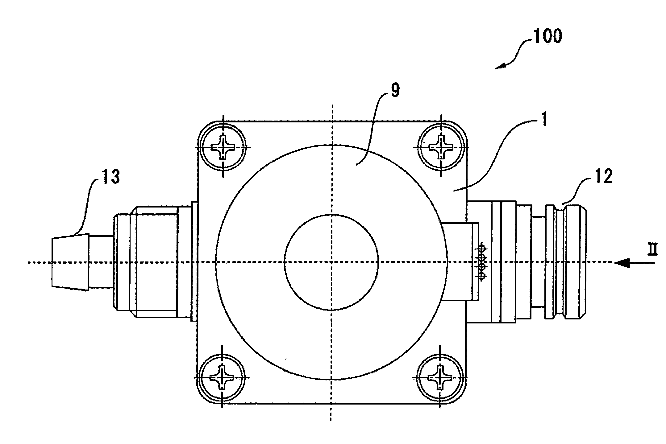
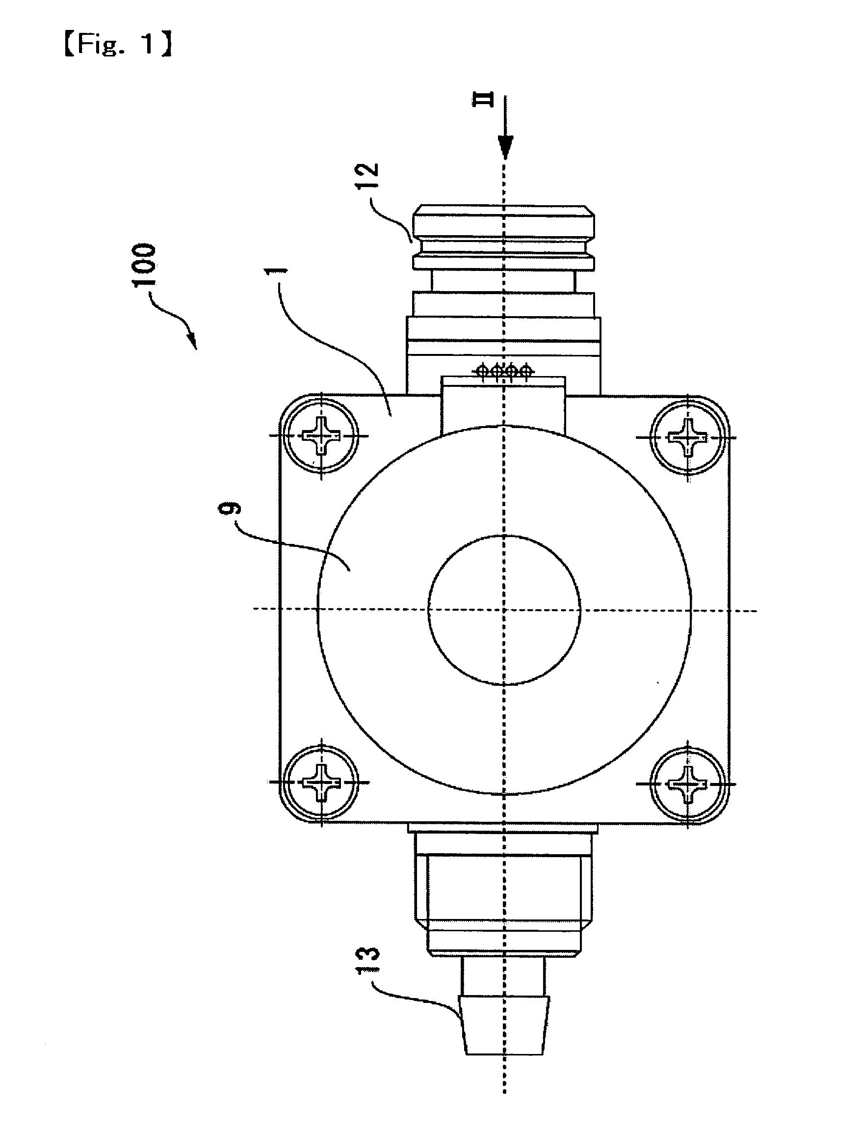
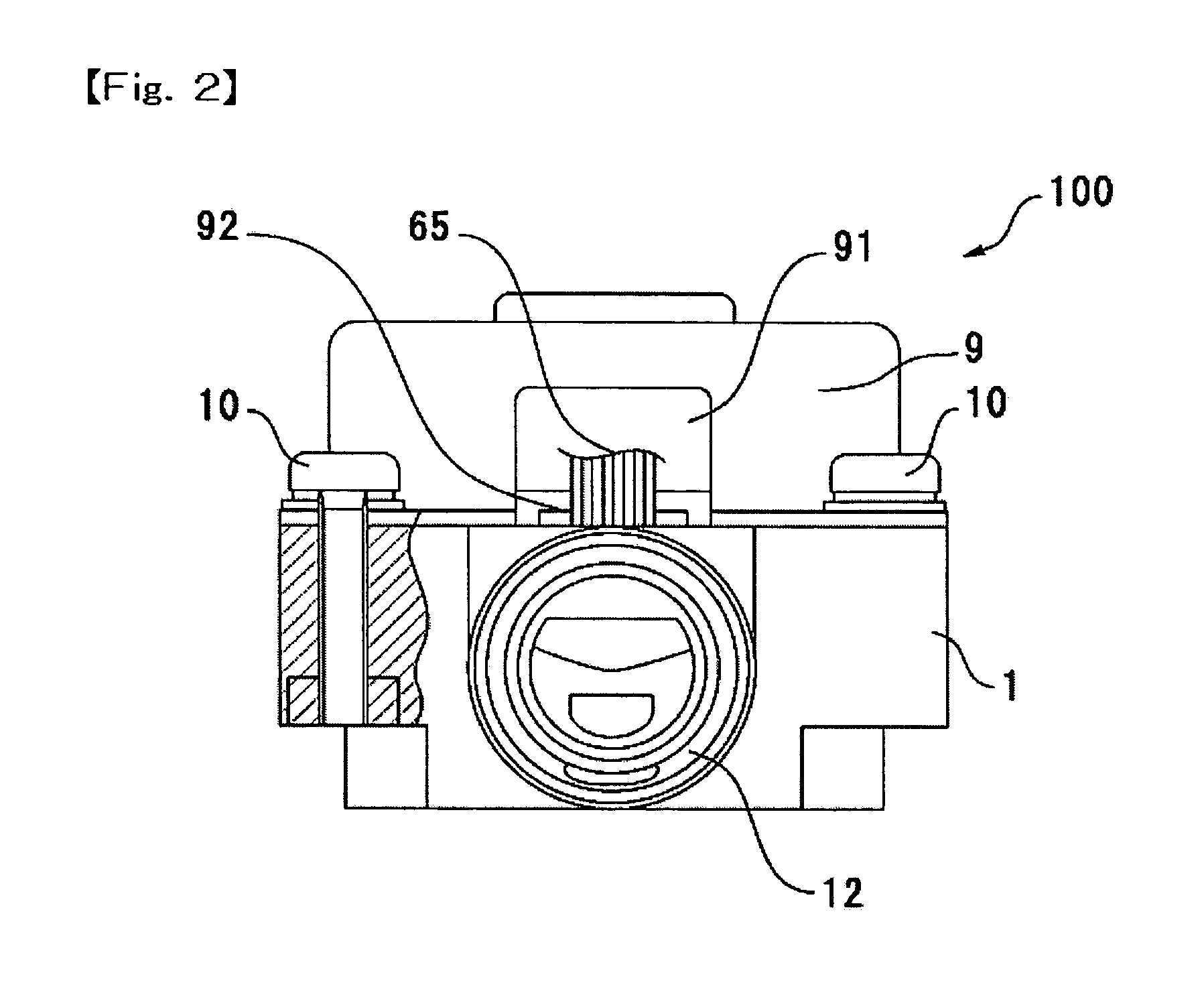
[0046]FIG. 1 is a plan view showing a small-sized hydraulic power generating device to which the present invention is applied. FIG. 2 is a side view of the small-sized hydraulic power generating device viewed from the direction shown by the arrow II in FIG. 1. FIG. 3 is a longitudinal sectional view showing the small-sized hydraulic power generating device shown in FIG. 1.

[0047] As shown in FIGS. 1, 2 and 3, a hydraulic power generating device 100 in accordance with a first embodiment of the present invention includes a main body case 1 provided with a fluid inlet port 12, a fluid outlet port 13 and a flow passage 110, a water wheel chamber 50 formed in the main body case 1, a support shaft 7 erected upwardly at a center position of the water wheel chamber 50, a rotation body 4 rotatably supported by the support shaft 7, a cup-shaped case 5 made of stainless steel which is mounted on the main body case 1 so as to enclose the rotati...

second embodiment

[0079] Second Embodiment

[0080] Next, a hydraulic power generating device in accordance with a second embodiment of the present invention will be described below with reference to FIGS. 8 through 11. The overall basic construction is the same as the construction of the first embodiment described above with reference to FIGS. 1 through 7. Therefore, the same constructional elements of the second embodiment are referred to as the same notational symbols of the above-mentioned first embodiment and only different construction is described below.

[0081] As shown in FIGS. 8, 9 and 10, a bearing hole 112 for supporting the lower end of the support shaft 7 is formed at a lower position of the water wheel chamber 50. The bearing hole 112 is formed on the upper face of a cylindrical boss 51 which is protruded from the bottom face 250 in the axial direction of the water wheel chamber 50. When the rotation body 4 is attached on the support shaft 7, a discharge space 25 is formed at the lower pos...


PUM


Abstract

A hydraulic power generating device includes a main body case forming a flow passage provided with a water wheel chamber between a fluid inlet port and a fluid outlet port, a cover covering the main body case, a water wheel for power generation disposed in the water wheel chamber, a rotor magnet for rotating in cooperation with the water wheel. An ejection port including a groove is formed on the main body case for ejecting fluid toward the blades of the water wheel at a high speed and an protrusion part is formed on the cover for adjusting the aperture area of the ejection port by entering into the groove. Further, a discharge space is formed at a downstream position of the water wheel chamber so as to be in communication with the fluid outlet port, to which fluid after having rotated the water wheel is ejected and a stagnation preventing protrusion part is formed in the discharge space to facilitate flow of air bubbles to the fluid outlet port.

Description

CROSS-REFERENCE TO RELATED APPLICATIONS [0001] This application claims priority to Japanese Application No. 2003-140958 filed May 19, 2003 and priority to Japanese Application No. 2003-140959 filed May 19, 2003, which are incorporated herein by reference. BACKGROUND OF THE INVENTION [0002] a) Field of the Invention [0003] The present invention relates to a hydraulic power generating device in which hydraulic power generation is performed by using the flow of city water ejected from a faucet or the like. [0004] b) Description of the Related Art [0005] An automatic faucet device has been spreading which is constructed such that water flows out from a faucet automatically when a hand is stretched out at a downward position of the faucet and a sensor detects it. Further, in recent years, a small-sized hydraulic power generating device has been provided at a midway position in the flow passage of city water to store electric power obtained by the hydraulic power generating device and to ...

Claims


Application Information

Patent Timeline
Patent Type & Authority Applications(United States)
IPC IPC(8): F03B13/00F03B13/10H02K7/18H02P9/04
CPCF03B13/00H02K7/1823F05B2240/911
Inventor YUMITA, YUKINOBUKUMAGAI, HIDEO
Owner SANKYO SEIKI MFG CO LTD
Learn More