Hard drive spindle motor controller with reverse current prevention

Active Publication Date: 2005-01-13
AVAGO TECH INT SALES PTE LTD
View PDF21 Cites 4 Cited by
  • Summary
  • Abstract
  • Description
  • Claims
  • Application Information

AI Technical Summary

Benefits of technology

[0007] The present invention is a motor controller for an electric motor having a plurality of motor terminals. The motor controller is connected to a power supply and comprises a commutation control, a current sensor, a peak target circuit, a pulse width control and a reverse current control. The commutation control is connected to the motor terminals for causing current pulses to flow through selected terminals during each commutation state. The current sensor provides a sense signal representative of the current pulses, and the peak current target circuit provides a target signal. The pulse width control controls pulse width of the current pulses as a function of the sense signal and the target signal. The reverse current control prevents reverse current from flowing into the power supply during change of commutation state.

Problems solved by technology

Typically, the off time during which both terminals are connected to the same voltage is not long enough for the motor current to decay completely to zero.
While commutating the motor and limiting the current with a one-shot (which allows motor current to decay for a fixed amount of time), a problem may occur at a commutation point.
If the motor is being driven in any given state by holding one terminal high, one terminal floated, and one terminal pulse width modulated low in order to control current, a problem may occur at a commutation of the high terminal.
This reverse current may cause stability problems for lower cost power supplies.
In the past, more expensive power supplies able to withstand the reverse current, or larger bypass capacitors able to absorb the reverse current were used to address this problem.
Both approaches result in a more expensive spindle motor system.

Method used


Image

  • Hard drive spindle motor controller with reverse current prevention
  • Hard drive spindle motor controller with reverse current prevention
  • Hard drive spindle motor controller with reverse current prevention

Examples


Embodiment Construction

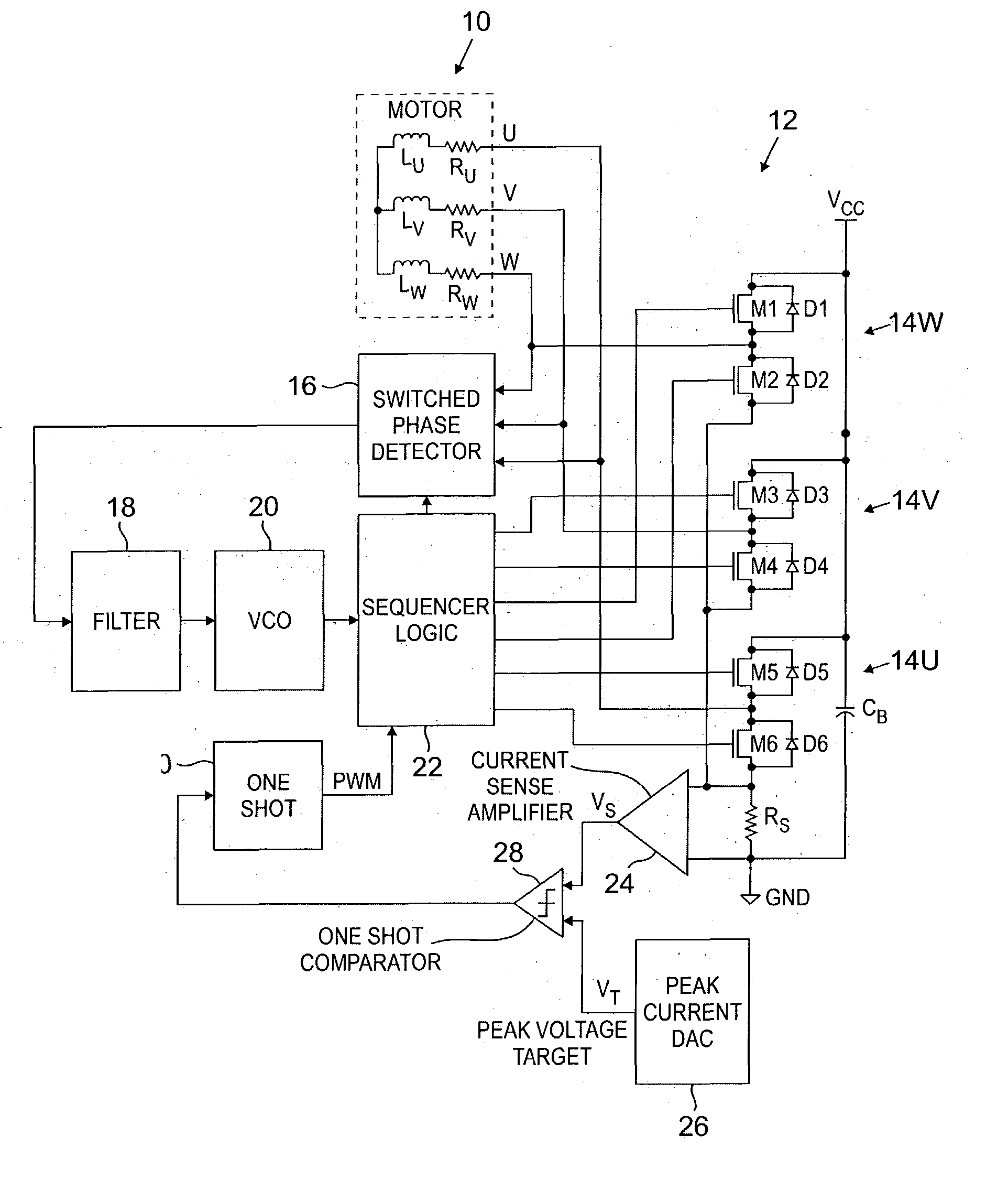
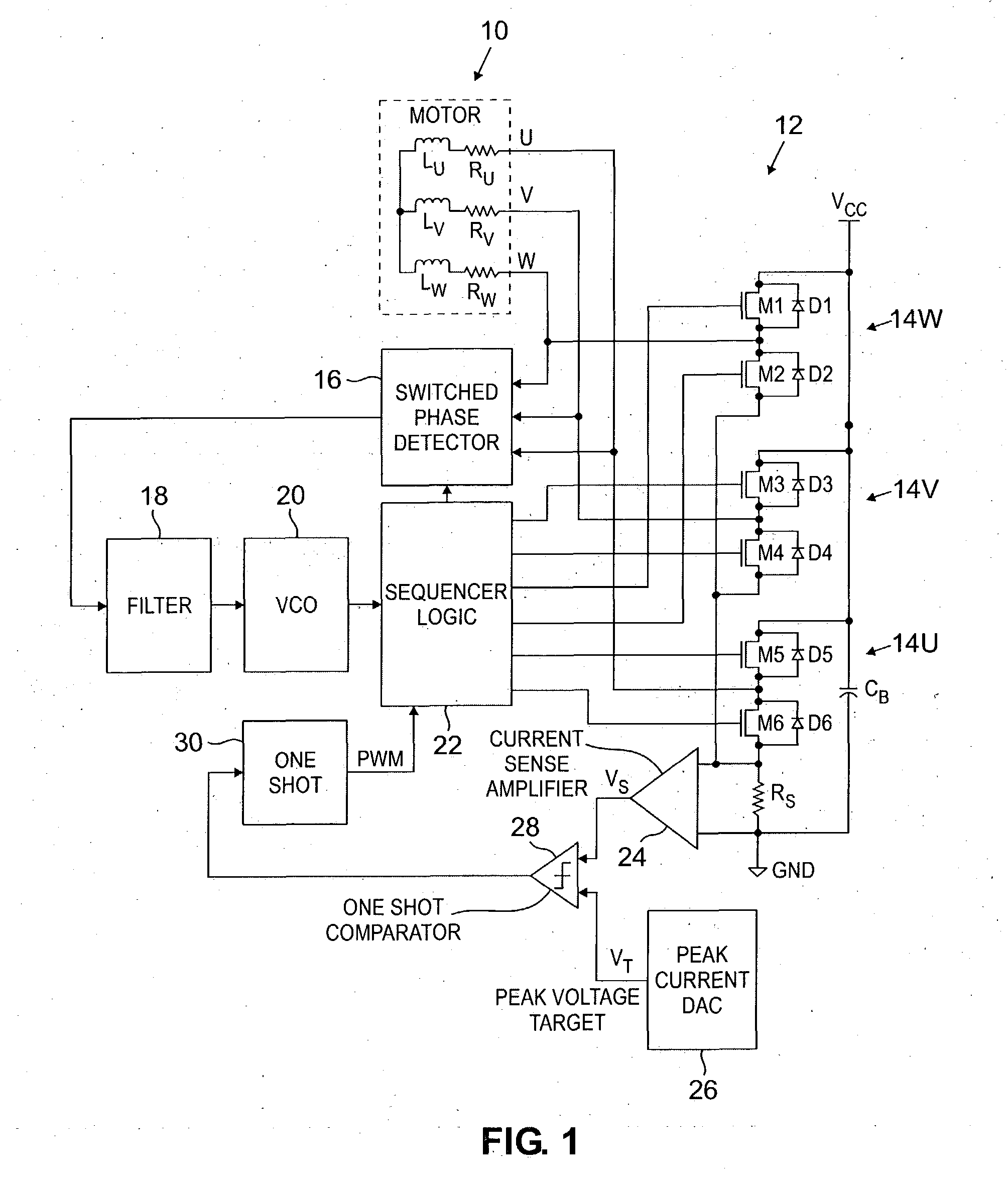
[0012]FIG. 1 is a block diagram showing three-phase motor 10 and prior art motor controller 12. Three-phase motor 10 is, for example, a spindle motor used in a hard disc drive. Prior art motor controller 12 allows motor 10 to spin up rapidly from a stopped condition to its normal operating speed using six-state commutation with peak current limiting. In some embodiments, once motor 10 approaches normal operating speed, a sinusoidal motor controller (not shown) takes over control of motor 10.

[0013] Three-phase motor 10 has three terminals labeled U, V, and W, three stator coils Lu, Lv, and Lw and associated internal resistance Ru, Rv, and Rw. As motor 10 spins, a voltage called the Back ElectroMotive Force (BEMF) is generated by moving the motor magnetic fields through coils Lu, Lv, and Lw. Voltages at terminals U, V, and W change due to this BEMF voltage. The three terminal voltages have the general shape of sinusoids, which are displaced by 120 degrees relative to each other. At t...


PUM


Abstract

A motor controller for an electric motor having a plurality of motor terminals is connected to a power supply and comprises a commutation control, a current sensor, a peak target circuit, a pulse width control and a reverse current control. The commutation control is connected to the motor terminals for causing current pulses to flow through selected terminals during each commutation state. The current sensor provides a sense signal representative of the current pulses, and the peak current target circuit provides a target signal. The pulse width control controls pulse width of the current pulses as a function of the sense signal and the target signal. The reverse current control prevents reverse current from flowing into the power supply during change of commutation state.

Description

CROSS-REFERENCE TO RELATED APPLICATION(S) [0001] None. BACKGROUND OF THE INVENTION [0002] The present invention relates to a control circuit for controlling operation of a three-phase motor. In particular, the present invention is a hard drive spindle motor controller which eliminates reverse current into the power supply during commutation. [0003] Spindle motors used in hard disc drives of computers are typically three-phase motors having three terminals. When a computer is first started, the hard drive spindle motor is typically spun up from a stopped condition by a motor controller circuit using six-state commutation, with peak current limiting and a relatively high motor current. To spin up the motor as quickly as possible, the start current is set as high as the hard drive power supply can deliver. In some systems, when the spindle motor approaches its normal operating speed, control of the spindle motor is transferred to a second motor controller circuit which provides sinusoi...

Claims


Application Information

Patent Timeline
CPCH02P6/14H02P6/002H02P6/28
Inventor BRENDEN, JASON P.PETERSON, MICHAEL J.
Owner AVAGO TECH INT SALES PTE LTD
Why Eureka
Try Eureka