Brushless and sensorless DC motor control system with locked and stopped rotor detection

a dc motor and control system technology, applied in the direction of motor/generator/converter stopper, electronic commutator, dynamo-electric converter control, etc., can solve the problems of insufficient duration and stop rotor to substantially affect the speed and torque of the motor

Active Publication Date: 2006-05-09
REGAL BELOIT AMERICA
View PDF24 Cites 185 Cited by
  • Summary
  • Abstract
  • Description
  • Claims
  • Application Information

AI Technical Summary

Benefits of technology

[0016]One advantage of the BLDC motor control locked and stopped detector is that rotor detection is provided without requiring a rotor position or speed sensor or relying on an over-current detection circuit. Another advantage of the present invention is that a commercially available, off-the-shelf motor control IC having a control input, for example, a current overload input port, may be utilized for switching on and off the driving of the phase coils and for most other aspects of motor control. Therefore, the present invention provides easy interfacing with existing motor control systems and motor control ICs. Yet another advantage of the present invention is that the fault detection circuit may include a microcontroller that is enabled by software, thus modifications to parameters and the control method can be easily made without hardware changes.
[0017]In one form, the present invention provides a motor control system for controlling a brushless and sensorless DC motor system having a plurality of phase coils, including: a motor control integrated circuit having a plurality of motor driver outputs and a control input for operating the plurality of output drivers, the plurality of motor driver outputs coupled to the plurality of phase coils; and a fault detection circuit coupled with the control input and capable of electively switching the state of said control signal to momentarily disable said plurality of out put drivers, said fault detection circuit is coupled to at least one of the plurality of phase coils and is capable of detecting a threshold back EMF voltage from the at least one of the plurality of phase coils.
[0018]In another form, the present invention provides a motor control system for controlling a brushless and sensorless DC motor system having a plurality of phase coils, including: a motor control integrated circuit having a plurality of motor driver outputs and a control input for operating the plurality of output drivers, said plurality of motor driver outputs coupled to the plurality of phase coils; and a fault detection circuit coupled with the control input and capable of detecting a plurality of electrical and nonelectrical fault conditions of the motor system, the fault detection circuit capable of providing a control signal to the control input to disable the plurality of output drivers upon detection of at least one of the plurality of electrical and nonelectrical fault conditions.
[0019]In another form, the present invention provides a method for detecting faults in a motor control system for a brushless and sensorless DC motor system having a plurality of phase coils, including the steps of: providing a motor control integrated circuit having a plurality of power drivers coupled to the plurality of phase coils, and having a control input capable of selectively enabling the plurality of power drivers; detecting a motor system fault by measuring EMF on at least on of the plurailty of phase coils; and switching the control input to disable the plurality of power drivers upon detecting a motor system fault, indicated by measured EMF below a present threshold thereby stopping motor operation.
[0020]In yet another form, the present invention provides a method for detecting a locked or stopped rotor in a motor control system for a brushless and sensorless DC motor system having a plurality of phase coils driven by power drivers, including the steps of: disabling the power drivers; then measuring the back EMF generated from the plurality of phase coils; and then enabling the power drivers after a time period dependent on the measured back EMF.
[0021]In another form, the present invention provides a fluid handling system, including: a pump; a brushless DC motor for driving the pump, the motor having a plurality of phase coils; and a motor control system coupled to the motor, the motor controller system including: a motor control circuit having at least one motor driver output coupled to the plurality of phase coils; and a microcontroller having an A / D converter coupled to at least one of the plurality of phase coils and having software enabling the micocontroller to provide an output signal coupled to the motor control circuit momentarily disabling the at least one motor driver output, the microcontroller capable of measuring a voltage level of back EMF generated in at least one of the plurality of phase coils upon the at least one motor driver output being disabled.

Problems solved by technology

In BLDC motor applications without a rotor position or other sensor, it is difficult to determine that the motor rotor has locked or that electronic commutation phase lock with the rotor has been lost by the motor control circuit, resulting in a stopped rotor.
The duration of momentarily disabling the driver outputs is of sufficient duration to allow at least one magnet to pass by a phase coil at the lowest motor speed, yet of insufficient duration to substantially effect motor speed and torque, for example about 1.0 msec.

Method used


Image

  • Brushless and sensorless DC motor control system with locked and stopped rotor detection
  • Brushless and sensorless DC motor control system with locked and stopped rotor detection
  • Brushless and sensorless DC motor control system with locked and stopped rotor detection

Examples


Embodiment Construction

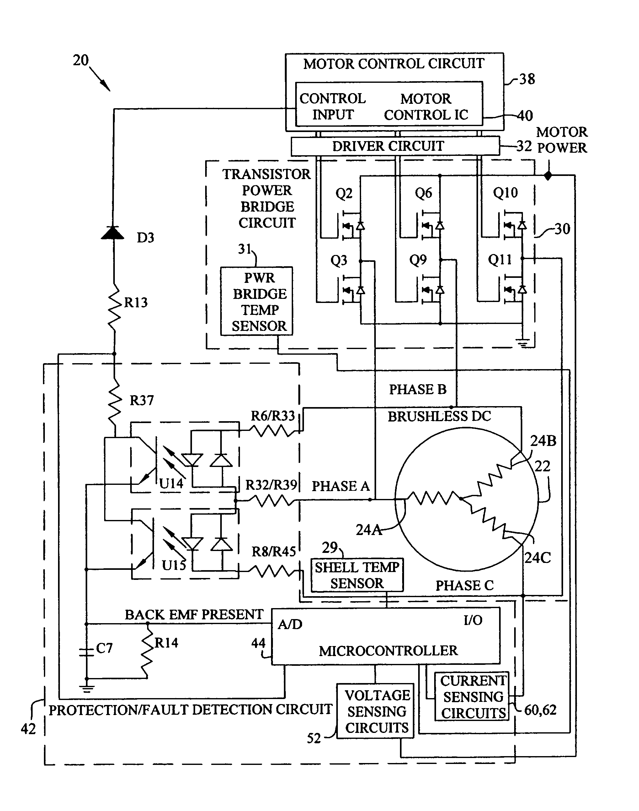
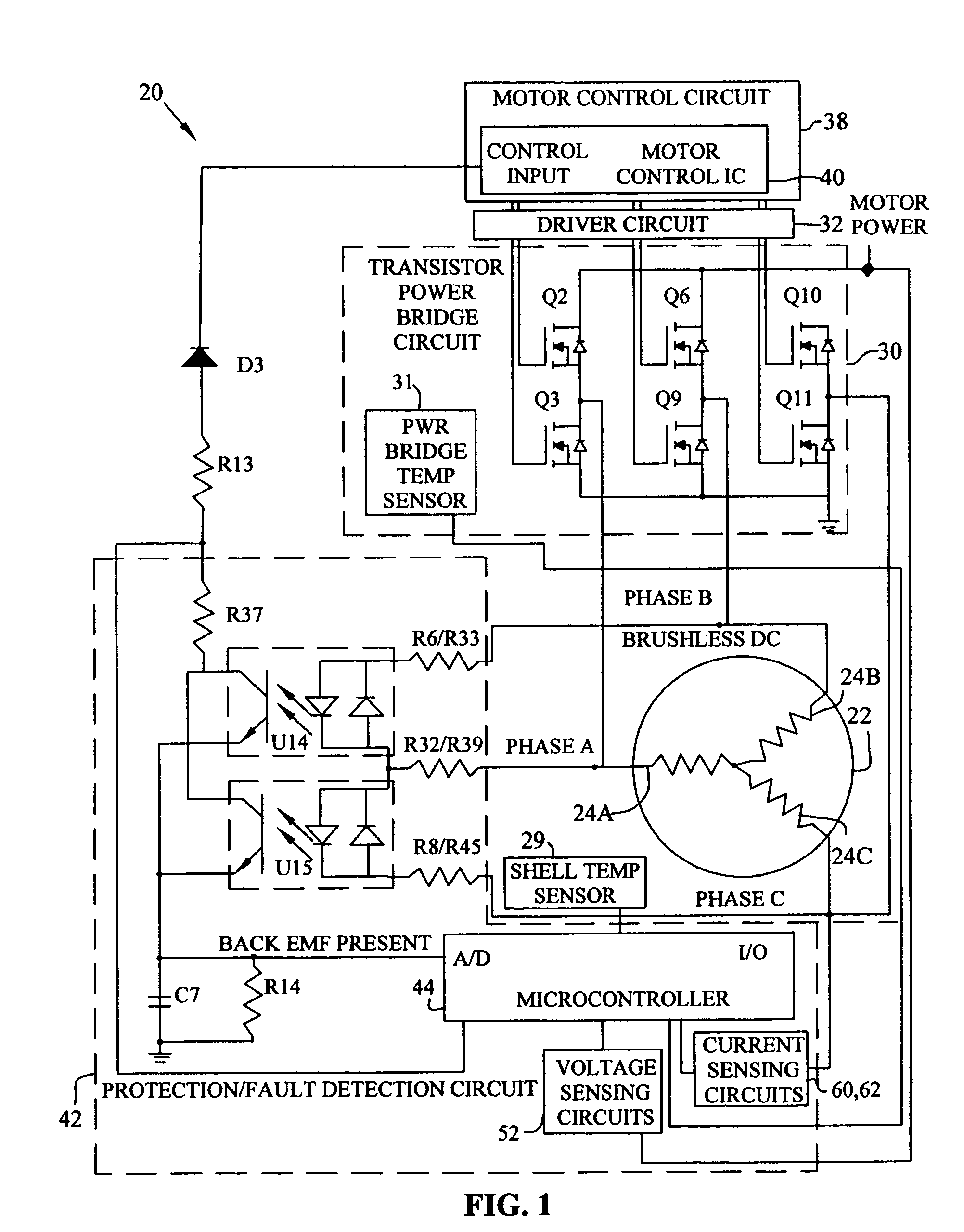
[0034]The present invention comprises a motor control system for controlling a brushless DC (BLDC) motor. Motor control system 20 is capable of detecting a locked or stopped rotor 26 without a rotor position or speed sensor. As depicted in FIG. 1, the exemplary embodiment of motor control system 20 generally includes electric motor 22, transistor power bridge circuit 30, phase driver circuit 32, motor control circuit 38, and protection / fault detection circuit 42.

[0035]Electric motor 22 in the exemplary embodiment is a BLDC motor having three phase coils, phase A 24a, phase B 24b, and phase C 24c. The plurality of phase coils 24a–24c are driven by transistor power bridge circuit 30, including phase source driving FETs Q2, Q6, and Q10, and phase sink driving FETs Q3, Q9, and Q11.

[0036]Transistor power bridge circuit 30 is controlled by motor control circuit 38, including motor control IC 40, which may be a commercially available, off-the-shelf motor control IC having a control input f...


PUM


Abstract

A motor control system for a brushless and sensorless DC motor for driving a compressor, pump or other application, includes a protection and fault detection circuit for detecting a locked rotor and a rotor which has stopped because of lost rotor phase lock. The motor control system also includes an off-the-shelf motor control integrated circuit having an input for disabling power outputs to the motor phase coils. The protection and fault detection circuit uses a back EMF sampling circuit coupled to the motor phase coils and momentarily disables power to the motor phase coils, via the motor control integrated circuit input, to determine if the motor rotor is rotating. The system also monitors supply voltage, supply current, temperature, and motor speed limits to detect faults and protect system components.

Description

CROSS REFERENCE TO RELATED APPLICATION[0001]This application claims the benefit under Title 35, U.S.C. § 119(e) of U.S. Provisional Patent Application Ser. No. 60 / 442,648, entitled BRUSHLESS AND SENSORLESS DC MOTOR CONTROL SYSTEM WITH LOCKED AND STOPPED ROTOR DETECTION, filed on Jan. 24, 2003.BACKGROUND OF THE INVENTION[0002]1. Field of the Invention[0003]The present invention relates to DC motor controllers, and, in particular, a motor control system that includes locked and lost rotor detection for a brushless and sensorless DC motor.[0004]2. Description of the Related Art[0005]For certain electric motor applications, such as driving a compressor or a pump, using DC motors is generally more advantageous then using AC motors. For example, compressor start-up requires a high torque at low speed start-up, which typically cannot be managed well by AC motors, especially AC motors having open loop controllers. Additionally, at lower compressor loads, the compressor may be more efficient...

Claims


Application Information

Patent Timeline
Patent Type & Authority Patents(United States)
IPC IPC(8): H02H5/04F04B35/04F04B49/02F04B49/06H02P6/00H02P6/08H02P6/12H02P6/18H02P29/02
CPCF04B35/04F04B49/02F04B49/065H02P6/12H02P6/182H02P29/02H02P6/001Y10S388/909H02P6/34
Inventor TERRY, ROBERT L.WYATT, ARNOLD G.
Owner REGAL BELOIT AMERICA
Why Eureka
Try Eureka