Optical sheet and LCD apparatus using the same

a technology of optical sheet and lcd, which is applied in the direction of lighting and heating apparatus, instruments, polarising elements, etc., can solve the problems of increasing the production cost of the lcd apparatus and the following problems of the conventional lcd apparatus, and achieve the effects of reducing the brightness preventing the shrinkage of the optical sheet, and enhancing the brightness

Active Publication Date: 2005-01-13
SAMSUNG DISPLAY CO LTD
View PDF7 Cites 32 Cited by
  • Summary
  • Abstract
  • Description
  • Claims
  • Application Information

AI Technical Summary

Benefits of technology

[0020] Accordingly, it is an aspect of the present invention to provide an optical sheet and an LCD apparatus using the same, in which a bright-line is decreased, brightness are enhanced, and the optical sheet is prevented from shrinking.

Problems solved by technology

However, the conventional LCD apparatus has following problems.
Third, the reflective polarizing film 164 enhances the brightness, but is relatively expensive, thereby increasing production cost of the LCD apparatus.

Method used


Image

  • Optical sheet and LCD apparatus using the same
  • Optical sheet and LCD apparatus using the same
  • Optical sheet and LCD apparatus using the same

Examples


first embodiment

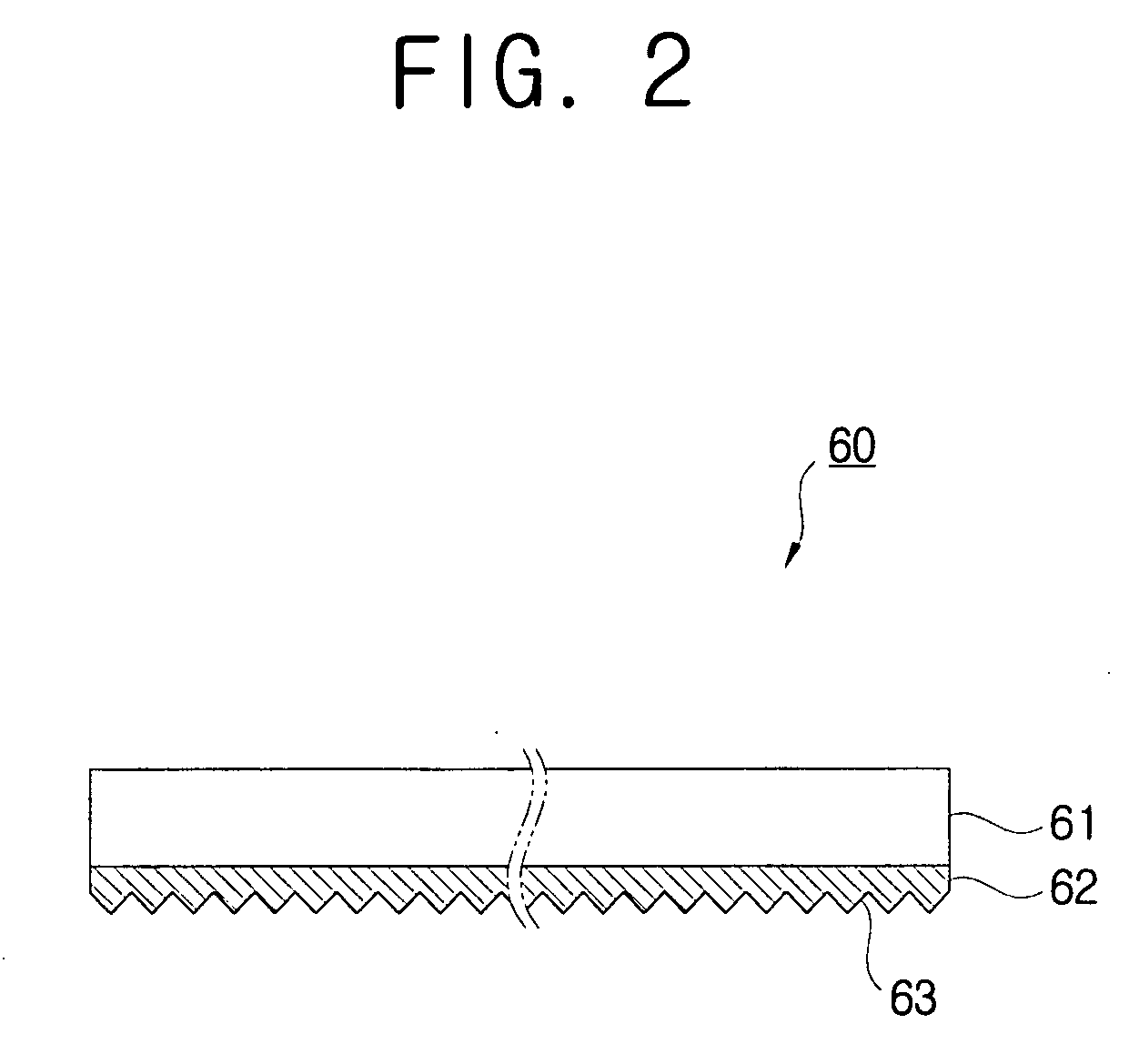
[0047] As shown in FIG. 2, an optical sheet 60 according to the present invention comprises a reflective polarizing layer 61 selectively transmitting and reflecting light, and a condensing layer 62 attached to one surface of the reflective polarizing layer 61 and condensing the light.

[0048] The reflective polarizing layer 61 selectively transmits and reflects the light. The reflective polarizing layer 61 is formed by layering films which have the same refractive index of an X-axis and are different in a refractive index of a Y-axis; therefore, X-axis vibrating components of the light can be transmitted through the X-axis, but the other components including Y-axis vibrating components are reflected. For example, P-wave components of the light from the lamp unit 130 are transmitted through the reflective polarizing layer 61, and S-wave components thereof are reflected from the reflective polarizing layer 61.

[0049] The condensing layer 62 is attached to the one surface of the reflecti...

sixth embodiment

[0059] Further, in the optical sheet 60e a diffusing part 65 is formed on the outer surface of the reflective polarizing layer 61. Therefore, the optical sheet 60e can prevent moire and rainbow patterns due to the condensing layer 62 from occurring in the LCD apparatus.

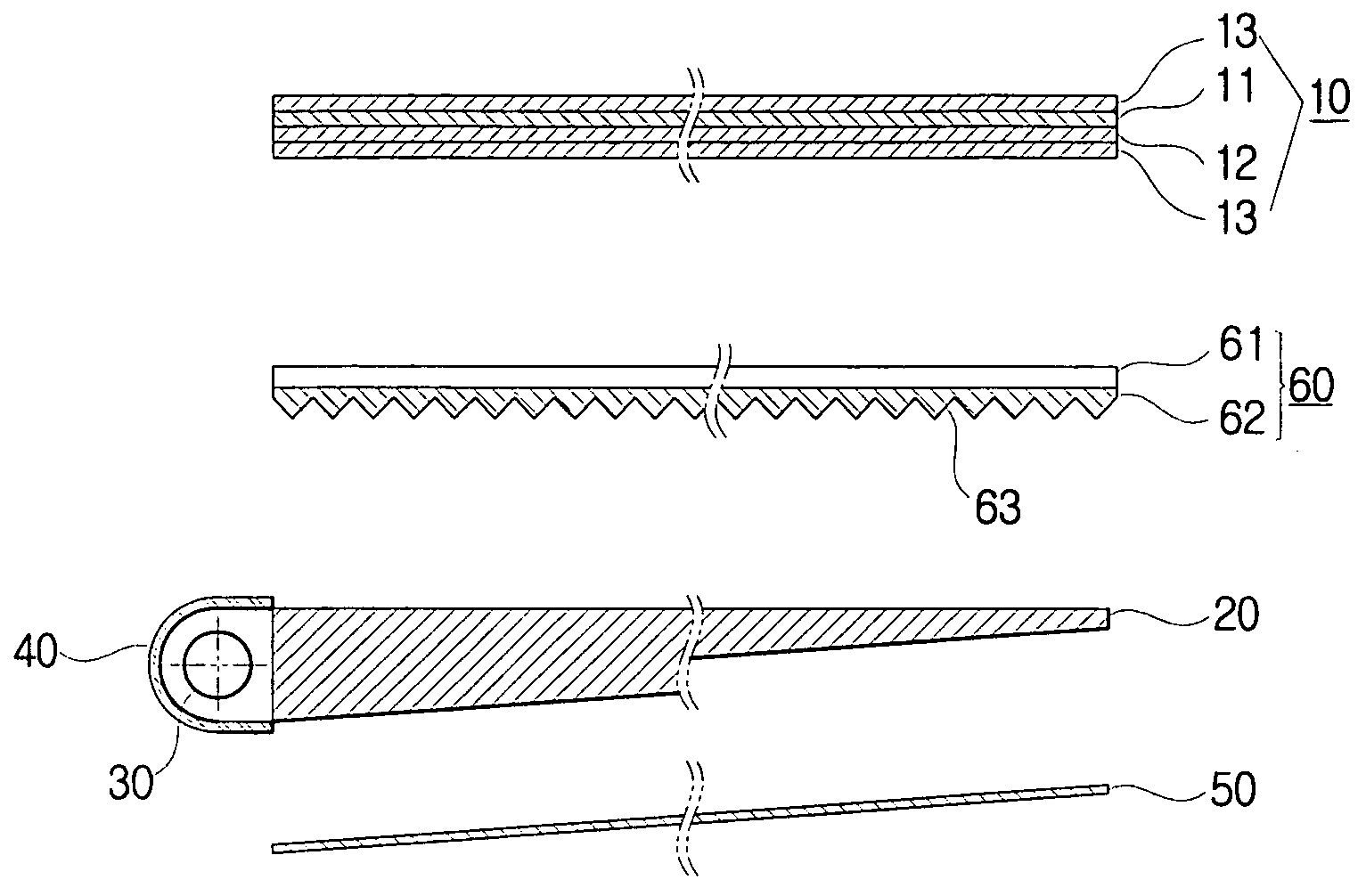
[0060] Hereinbelow, an LCD apparatus according to a first embodiment of the present invention using the above-described optical sheets will be described with reference to FIG. 8, wherein the optical sheet 60 according to the first embodiment is exemplarily used.

[0061] An LCD apparatus according to the first embodiment comprises an LCD panel 10 to display images thereon, a lamp unit 30 emitting light, a light guide plate 20 to guide the light from the lamp unit 30 toward the LCD panel 10 evenly, and a reflector 50 provided behind the light guide plate 20 and reflecting the light arriving at the reflector 60 into the light guide plate 20. Further, the LCD apparatus according to the first embodiment comprises the optic...


PUM

PropertyMeasurementUnit
hazeaaaaaaaaaa
inclination angleaaaaaaaaaa
brightnessaaaaaaaaaa

Abstract

The present invention relates to an optical sheet and an LCD apparatus using the same. An LCD apparatus according to the present invention comprises an LCD panel to display a picture thereon; a lamp unit emitting light; a light guide plate to guide the light from the lamp unit toward the LCD panel evenly; an optical sheet provided between the LCD panel and the light guide plate and including a condensing layer condensing the light from the light guide plate on the LCD panel, and a reflective polarizing layer attached to the surface of the condensing layer facing the LCD panel and selectively transmitting and reflecting the light condensed by the condensing layer. With this configuration, the present invention provides an optical sheet and an LCD apparatus using the same, in which a bright-line is decreased, brightness are enhanced, and the optical sheet is prevented from shrinking.

Description

CROSS-REFERENCE TO RELATED APPLICATIONS [0001] This application claims the benefit of Korean Patent Application No. 2003-013757, filed Mar. 5, 2003, in the Korean Intellectual Property Office, the disclosure of which is incorporated herein by reference. BACKGROUND OF THE INVENTION [0002] 1. Field of the Invention [0003] The present invention relates to an optical sheet and an LCD (liquid crystal display) apparatus using the same, and more particularly, to an LCD apparatus in which a bright-line is decreased, brightness are enhanced, and the optical sheet is prevented from shrinking. [0004] 2. Description of the Related Art [0005] An LCD apparatus employs the principle that a molecular arrangement of liquid crystal is varied when voltage is applied to the liquid crystal. The varied molecular arrangement causes double refraction, optical rotatory power, optical scattering, etc., thereby forming visible images. In other words, the LCD device displays the images by controlling the inten...

Claims


Application Information

Patent Timeline
Patent Type & Authority Applications(United States)
IPC IPC(8): G02B5/04F21V8/00F21Y103/00G02B5/30G02F1/1335G02F1/13357
CPCG02B6/0053G02F1/133615G02B6/0056G02F1/1335
Inventor LEE, JEONG-HWANHAN, BYUNG-WOONGPARK, JONG-DAEKIM, DONG-HOONKIM, MING-GYU
Owner SAMSUNG DISPLAY CO LTD
Why Eureka
Try Eureka