Optical read device, information processing device using optical recording medium, and information reproduction method

Inactive Publication Date: 2005-01-13
SONY CORP
View PDF4 Cites 1 Cited by
  • Summary
  • Abstract
  • Description
  • Claims
  • Application Information

AI Technical Summary

Benefits of technology

[0014] According to the present invention, despite a positional deviation in a returning light spot on the split light-receiving device, one of the split lines can be selected depending on the position of the light spot to calculate the difference between two signals received on detection areas delimited by the selected split line, thereby eliminating the common-mode components.

Problems solved by technology

A signal containing address information (address signal) is more difficult to detect after data is written onto a disk, in which case disturbance from pits (record marks) affects the detection, than before the data is written onto the disk.
For this reason, elimination of common-mode components is not satisfactory in the presence of a shift of the light spot towards either side from the center of the two-split detector, such as when the spot S lies biased towards the area B (as shown in FIG. 12A) or the area A (as shown in FIG. 12C) of the detector.
If a shift in an objective lens due to, for example, deflection causes the light spot on the two-split detector to be positionally deviated, signals of respective amounts of light become unbalanced, preventing satisfactory elimination of RF components from the signals.
As an unfortunate result, it becomes difficult to acquire recorded address information or the structure of detection circuits becomes complicated.

Method used


Image

  • Optical read device, information processing device using optical recording medium, and information reproduction method
  • Optical read device, information processing device using optical recording medium, and information reproduction method
  • Optical read device, information processing device using optical recording medium, and information reproduction method

Examples


Embodiment Construction

[0027] The present invention relates to optical reading units where light is radiated onto an optical recording medium, information processing apparatuses using an optical recording medium (for example, recording / playback apparatuses), and an information playback method. The present invention assumes that returning light from an optical recording medium is detected to acquire a push-pull signal, and is preferably applicable to, for example, an optical recording medium having address information recorded as wobble information, where the address information contained in a push-pull signal is played back.

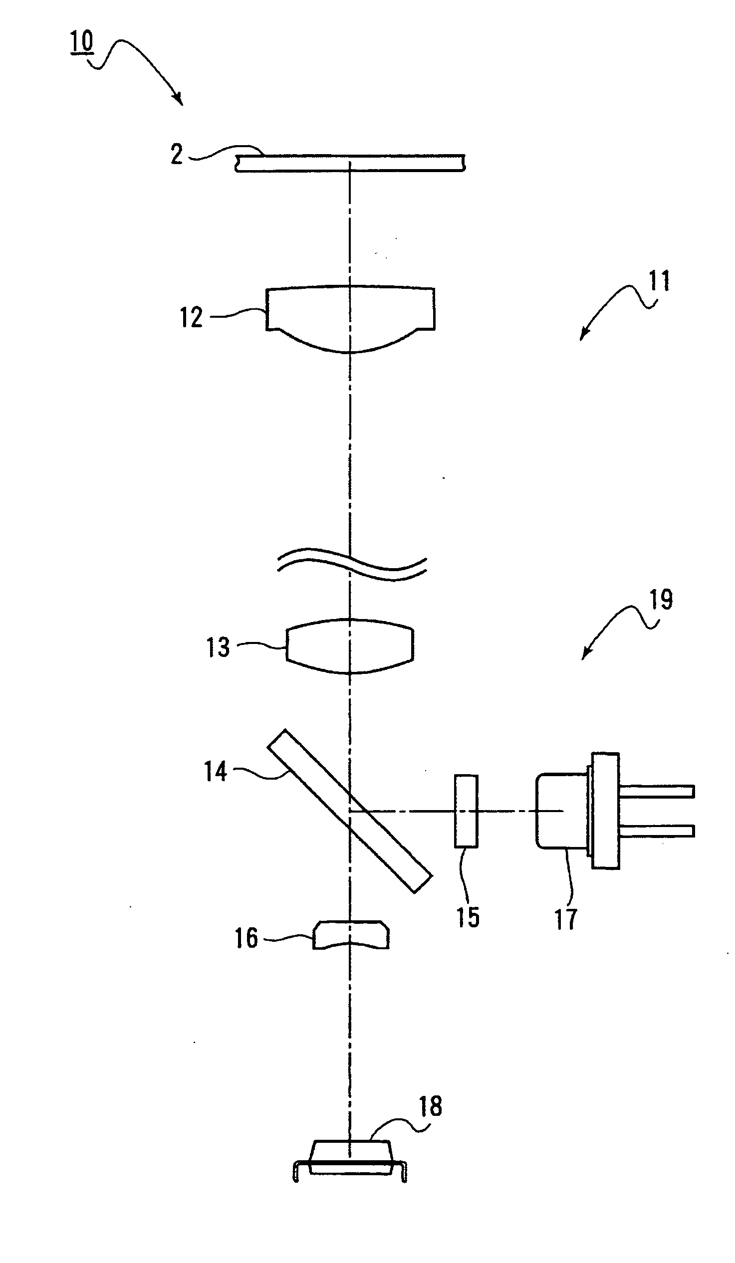
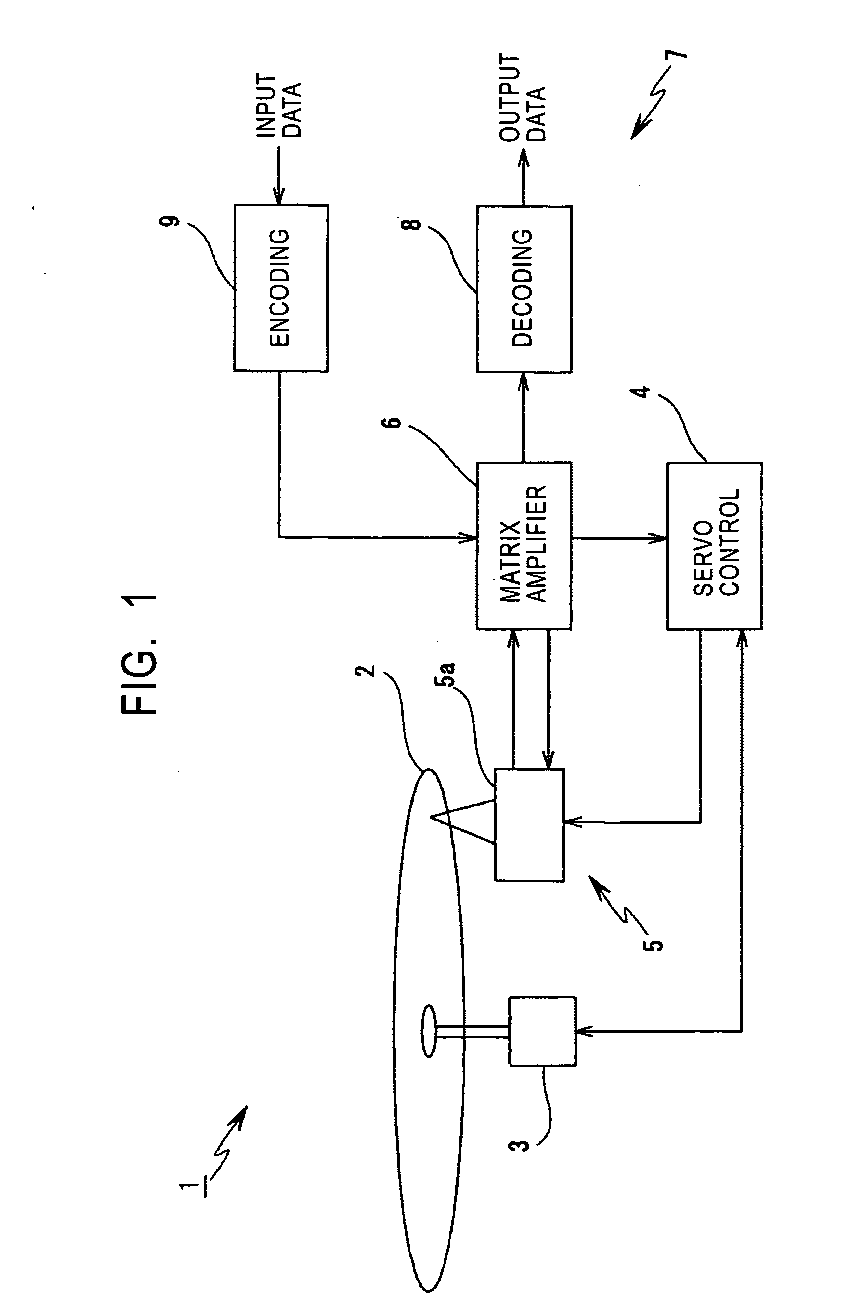
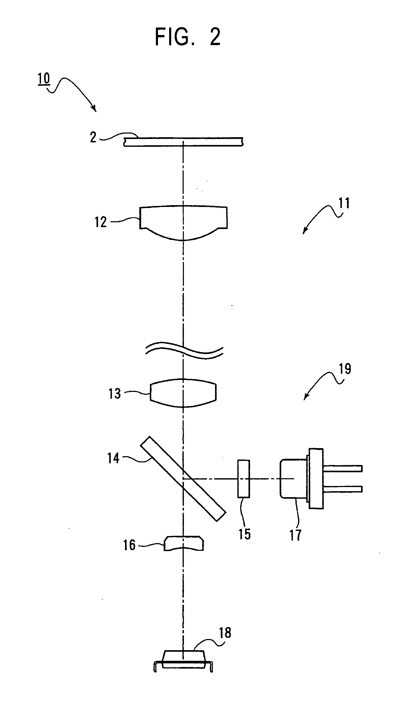
[0028]FIG. 1 shows a basic structure according to the present invention, illustrating an exemplary structure of an optical disk recording / playback apparatus.

[0029] An optical recording medium 2 used in an information processing apparatus 1 has various types of information, including user data, recorded thereon, and such information is read out using laser beam radiation.

[0030] The p...


PUM


Abstract

An optical reading unit which ensures that address information recorded as guide groove wobbles on an optical recording medium is easily played back. A light-receiving device (20) for detecting returning light from the optical recording medium has detection areas (21A to D) delimited by a plurality of split lines (22), (23), and (24). The position of one of the split lines functioning as a detection reference line is changed according to the position of a returning light spot S on a light-receiving surface (21) of the light-receiving device (20) and push-pull signals (PP1 to 3) are acquired by calculating the difference between signals received on two detection areas delimited by the split line to eliminate common-mode components.

Description

TECHNICAL FIELD [0001] The present invention relates to a technology for satisfactorily eliminating common-mode components occurring when a push-pull signal is generated in an apparatus utilizing an optical recording medium and detecting address information contained in such a push-pull signal by using a split light-receiving device which has a light-receiving surface divided by a plurality of split lines and by selecting one of the split lines according to the position of the light spot on the light-receiving surface, thus overcoming a problem with the push-pull method (that is, a problem of DC offset, which occurs when the center of a returning light spot does not coincide with the center of the split light-receiving device). BACKGROUND ART [0002] Recording / playback apparatuses using optical recording media such as compact disks (CDs) and digital versatile disks (DVDs) are known. Information-writable optical disks such as CD-R / RW, DVD+RW, and DVR have address information recorded ...

Claims


Application Information

Patent Timeline
IPC IPC(8): G11B7/005G11B7/09G11B7/13G11B7/133
CPCG11B7/0053G11B7/133G11B7/094G11B7/0903G11B7/005G11B7/09
Inventor IIMURA, SHINICHIRO
Owner SONY CORP
Why Eureka
Try Eureka