Hard disk drive preamplifier write driver

a write driver and hard disk drive technology, applied in the direction of h-bridge head driver circuit, data recording, instruments, etc., can solve the problem of damage or destruction of sensitive read element(s), damage to adjacent read elements, and difficulty in programming the mid-supply voltage, which is typically only 1 bit programmabl

Inactive Publication Date: 2005-01-13
TEXAS INSTR INC
View PDF7 Cites 8 Cited by
  • Summary
  • Abstract
  • Description
  • Claims
  • Application Information

AI Technical Summary

Benefits of technology

[0011] The present invention achieves technical advantages as a HDD preamplifier write driver that overcomes the problems and limitations associated with the prior art apparatuses. The present invention moves the common-mode voltage of the writer's output inversely proportional to the programmed write current. As such, the common-mode voltage is fixed independent of the programmed write current. Further, the present invention provides more constant overshoot independent of the programmed write current.

Problems solved by technology

The read sensors consist of very sensitive magnetoresistive material that cannot tolerate excessive voltages.
Because of the close spacing of the writer and the reader, an asymmetrical voltage swing provided to the write head can couple into and damage the adjacent read element.
Prior art apparatuses for use in applying write signals for driving a write head to effect writing information to a memory device, such as write driver preamplifiers, are often not designed to effect symmetrical voltage swing during the write current reversal period.
Any voltage asymmetry in carrying out write current reversal will result in energy coupling into the adjacent reader(s), and can damage or destroy the sensitive read element(s).
Further limitations of these prior art apparatuses include the difficulty in programming the mid-supply voltage which is typically only 1 bit programmable.

Method used


Image

  • Hard disk drive preamplifier write driver
  • Hard disk drive preamplifier write driver
  • Hard disk drive preamplifier write driver

Examples


Embodiment Construction

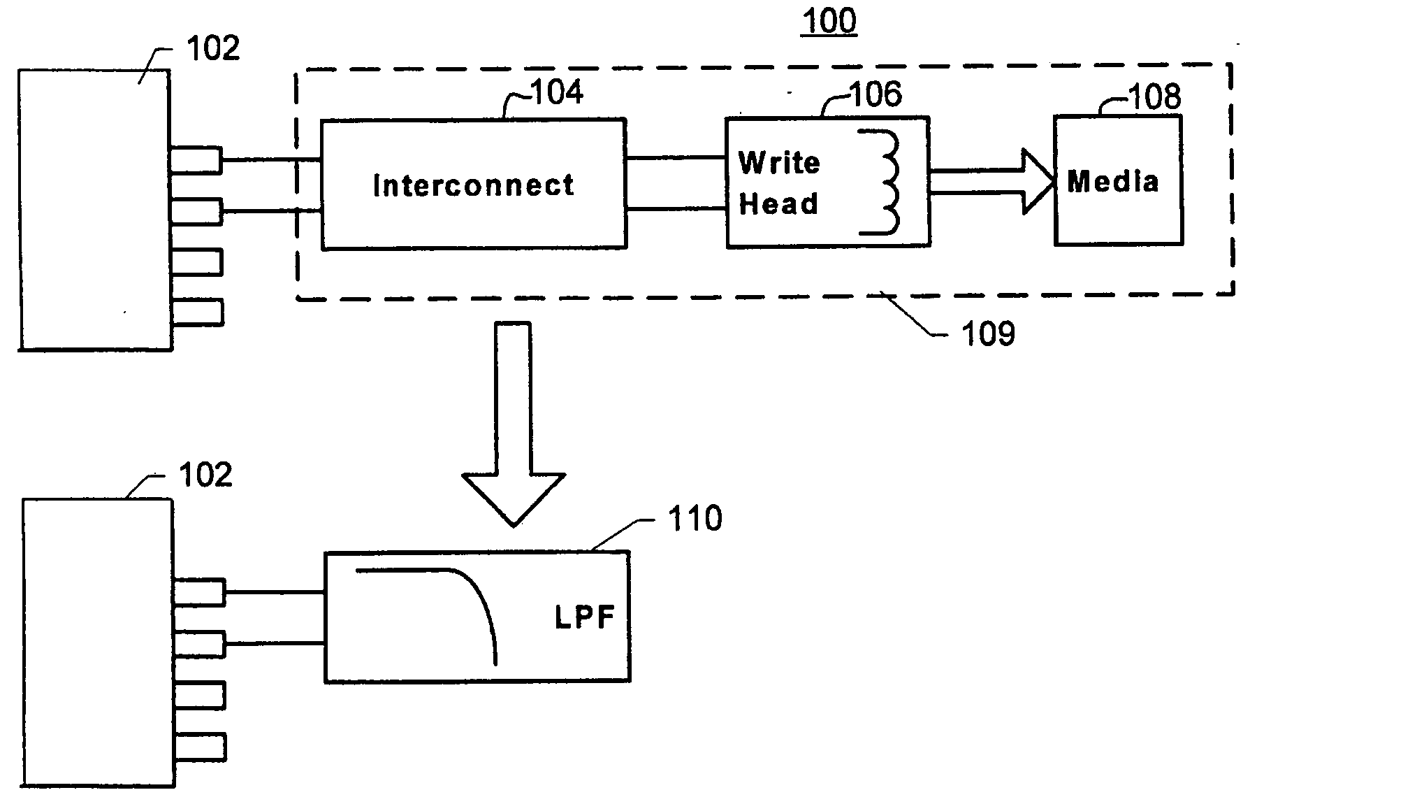
[0021]FIG. 1 is a schematic diagram illustrating modeling of a thin film inductive write driver system as a low pass filter. In FIG. 1, a write driver system 100 includes a preamplifier 102 coupled with an interconnect structure 104. Interconnect structure 104 typically includes lead wires extending from preamplifier 102 along an extended arm reaching adjacent a magnetic storage disk (not shown in FIG. 1) to a write head 106. Write head 106 is typically suspended on the extended arm that supports interconnect structure 104 in close proximity with media 108. Media 108 is typically a magnetic storage disk.

[0022] Components contained within dotted line box 109 may be modeled as a low pass filter (LPF) 110 coupled with preamplifier 102. Low pass filter 110 is configured to pass signals having frequencies below a predetermined frequency value and inhibit passing of signals having frequencies above the predetermined frequency value.

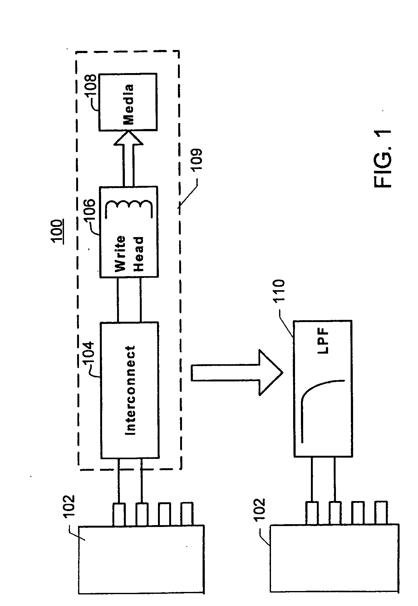
[0023]FIG. 2 is a schematic diagram illustrating how a ...


PUM

PropertyMeasurementUnit
currentaaaaaaaaaa
voltageaaaaaaaaaa
polarityaaaaaaaaaa

Abstract

The present invention discloses an apparatus (160) comprising a common mode generator circuit (162) coupled to a current directing circuit adapted to provide current to a first write head connection node (170) and to a second write head connection node (172). The common mode generator circuit (162) is adapted to provide additional current to the first write head connection node (170) and to the second write head connection node (172), wherein the first write head connection node (170) is adapted to produce a first write signal, wherein the second write head connection node (172) is adapted to produce a second write signal, wherein the current and the additional current are adapted to establish a voltage across the first write head connection node (170) and the second write head connection node (172), wherein the voltage is adapted to be pulled toward a first polarity based on the first write signal and toward a second polarity based on the second write signal, and wherein the voltage pulled toward the first polarity and the voltage pulled toward the second polarity are substantially centered about a common mode voltage.

Description

FIELD OF THE INVENTION [0001] The present invention relates to inductive line drivers and, more particularly, to a differential thin-film inductive-write driver for use with a hard disk drive (HDD) preamplifier. BACKGROUND OF THE INVENTION [0002] The interconnecting leads between preamplifiers and read / write heads in hard disk drive devices are spaced very close together, often within a few mils of each other. The read sensors consist of very sensitive magnetoresistive material that cannot tolerate excessive voltages. In contrast, the write element consists of a thin-film inductor which requires large sub-nanosecond voltage swings for high data rate systems. Because of the close spacing of the writer and the reader, an asymmetrical voltage swing provided to the write head can couple into and damage the adjacent read element. [0003] Prior art apparatuses for use in applying write signals for driving a write head to effect writing information to a memory device, such as write driver p...

Claims


Application Information

Patent Timeline
Patent Type & Authority Applications(United States)
IPC IPC(8): G11B5/012
CPCG11B5/022G11B5/012
Inventor BLOODWORTH, BRYAN E.EATON, THOMAS COUGAR VAN
Owner TEXAS INSTR INC
Why Eureka
Try Eureka