
Power adapter interface circuitry for protecting a battery operated system

a power adapter and electronic system technology, applied in emergency protective circuit arrangements, electrical devices, and arrangements responsive to excess voltage, etc., can solve problems such as user safety hazards, severe damage, and most prior art protection schemes lacked reliable anti-bounce circuitry

Active Publication Date: 2005-01-13
ANALOG DEVICES INC
View PDF5 Cites 37 Cited by
  • Summary
  • Abstract
  • Description
  • Claims
  • Application Information

AI Technical Summary

Benefits of technology

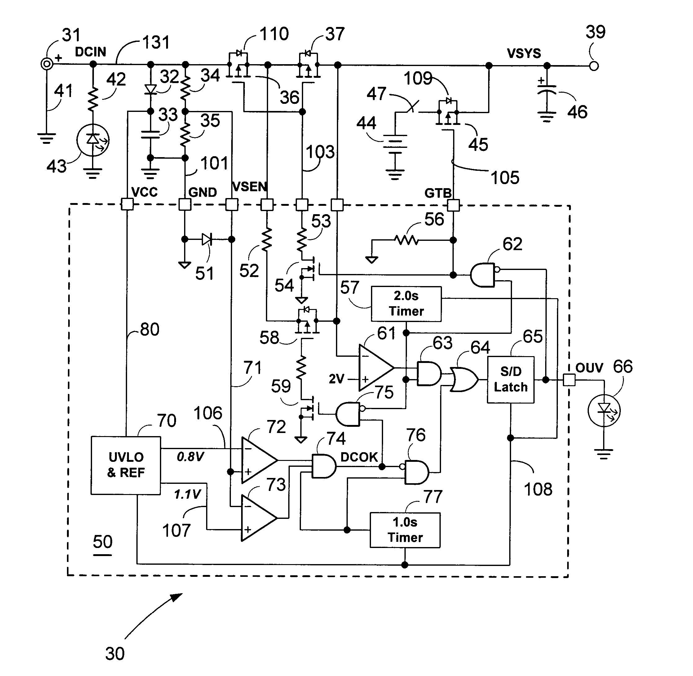
[0005] Adapter interface circuitry has series connected first and second electronic switches for coupling an adapter output voltage to a system power input. A sense voltage is generated that is proportional to the adapter output voltage. Likewise, a capacitor is charged to a capacitor voltage if the adapter output voltage has a preferred polarity. A battery, with internal short circuit protection, is coupled to the system power input with a third electronic switch. In one embodiment of the present invention, an integrated circuit (IC) contains the circuitry for generating controls for the switches as well as generating signal outputs. When the capacitor voltage exceeds a predetermined value, two timers are enabled and started, and a shutdown latch is enabled. The sense voltage is used in a window comparator to determine if the adapter voltage is within a predetermined range. When the adapter voltage output is within the predetermined range, a power correct signal is generated indicating an in-range adapter output voltage condition. If the adapter output voltage is not in-range, then the shutdown latch is set at the end of the first timer interval and a light emitting diode (LED) is turned ON indicating an out-of-range voltage condition. If the adapter output voltage is in-range and the second timer interval has not expired, then a first switch voltage within the series connected switches is coupled to the system input to determine if there is a short circuit condition within the system. If the first switch voltage is below a predetermined level after the second timer interval, then the shutdown latch is again set indicating a fault condition. If the adapter output voltage is within a desired range and there is no short circuit condition after the second timer interval, then the first and second electronic switches are turned ON thereby coupling the adapter output voltage to the system power input. Likewise, the third electronic switch is turned OFF decoupling the battery from the system power input.

Problems solved by technology

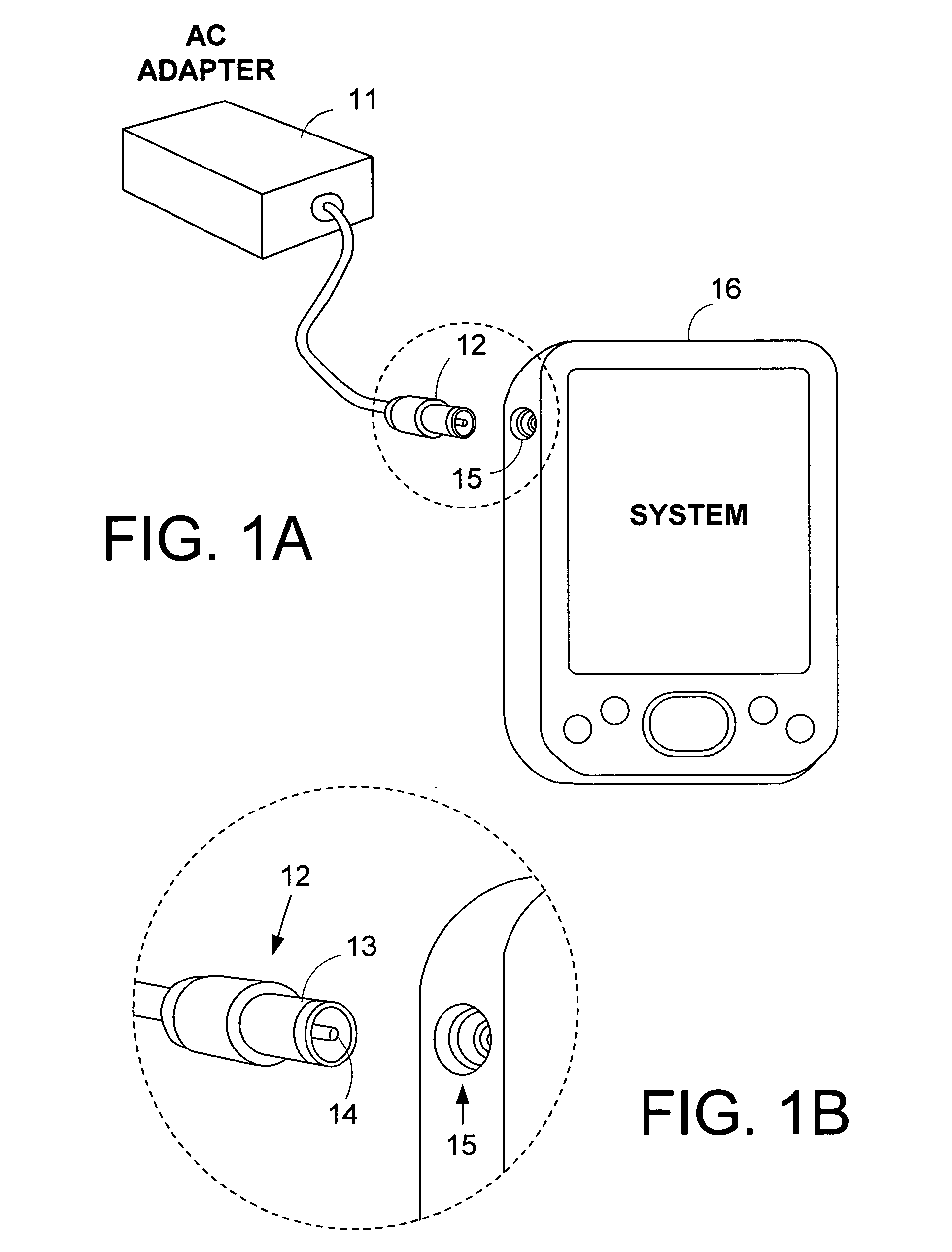
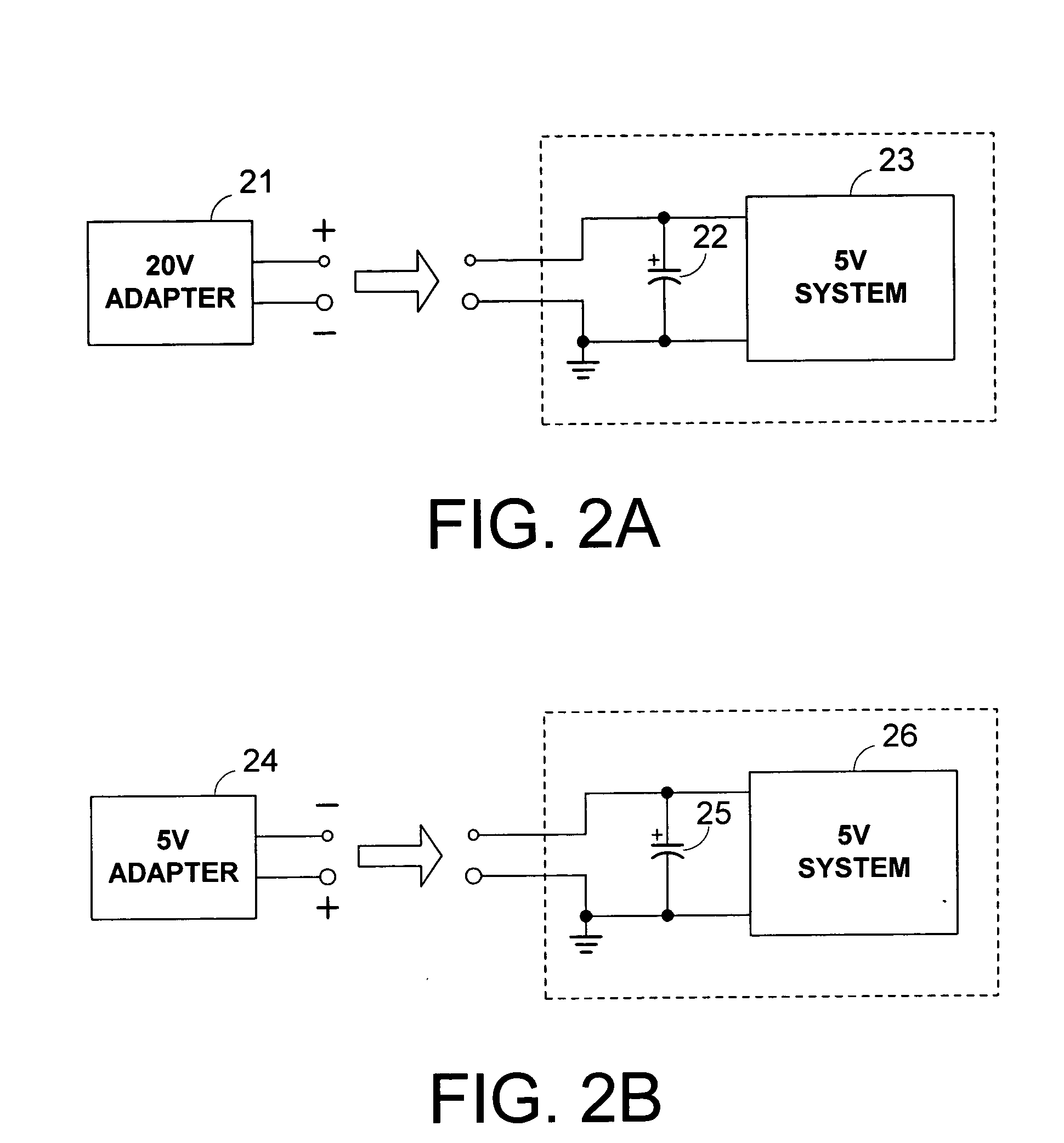
There is a substantial likelihood that an adapter designed for one system having a particular voltage level may be accidentally plugged into another system with a different voltage level.
An adapter with a high voltage level or a reversed polarity connector could cause severe damage if it is used to power a non-compatible host system.
In certain cases, it may also result in safety hazards to a user.
In addition, most prior art protection schemes lacked reliable anti-bounce circuitry.
Intermittent contact or bouncing contacts during the initial plug-in period often leads to false triggering of the protection circuitry.
Furthermore, the prior art protection schemes generally do not provide a proper interface that prevents a host system from being coupled to an adapter with incompatible voltage levels or polarities.

Method used


Image

  • Power adapter interface circuitry for protecting a battery operated system
  • Power adapter interface circuitry for protecting a battery operated system
  • Power adapter interface circuitry for protecting a battery operated system

Examples


Embodiment Construction

[0016] In the following description, numerous specific details are set forth to provide a thorough understanding of the present invention. However, it will be obvious to those skilled in the art that the present invention may be practiced without such specific details. In other instances, well-known circuits may be shown in block diagram form in order not to obscure the present invention in unnecessary detail. For the most part, details concerning timing considerations and the like have been omitted in as much as such details are not necessary to obtain a complete understanding of the present invention and are within the skills of persons of ordinary skill in the relevant art.

[0017] Refer now to the drawings wherein depicted elements are not necessarily shown to scale and wherein like or similar elements are designated by the same reference numeral through the several views. In the following descriptions, the terms alternating current (AC) adapter may be used interchangeable with t...


PUM


Abstract

An integrated circuit (IC) has logic and timing circuits that are coupled to discrete circuitry to provide protection and indications whenever an AC adapter that is faulty or has improper voltage levels or polarity are plugged into a system. In particular, the IC device provides over-voltage, under-voltage, and reversed-polarity protections to an electronic system to keep the electronic system from being damaged by an alternating current (AC) adapter having an improper voltage range or voltage polarity. It also provides a protection that prevents an adapter from powering a host system that has a short-circuit fault.

Description

TECHNICAL FIELD [0001] The present invention generally relates to a protection device for a battery-powered electronic system. In particular, it relates to an integrated circuit (IC) device providing over-voltage, under-voltage, and reversed-polarity protections to an electronic system to keep the electronic system from being damaged by an alternating current (AC) adapter having an improper voltage range or voltage polarity. It also provides a protection that prevents an adapter from powering a host system that has a short-circuit fault. BACKGROUND INFORMATION [0002] There are many types of electronic systems powered by AC to direct current (DC) adapters including, printers, scanners, liquid crystal display (LCD) monitors, personal computer (PC) speakers, digital subscriber line (DSL) modems, etc. There are also many types of portable electronic systems that may be powered by either internal batteries or AC adapters, such as cellular phones, digital cameras, compact disc (CD) player...

Claims


Application Information

Patent Timeline
Patent Type & Authority Applications(United States)
IPC IPC(8): H02H3/20H02H11/00
CPCH02H3/202H02H11/002H02H3/207
Inventor LIU, KWANG H.NEGRU, SORINHSIEH, GEORGECHEN, JACKYSHIH, FRANKWU, SCOTT
Owner ANALOG DEVICES INC
Learn More