Phase synchronization circuit

a phase synchronization and circuit technology, applied in the field of phase synchronization circuits, can solve the problems of circuits with large oscillation frequency variation, voltage controlled oscillation circuits, and inability to easily perform frequency acquisition to the desired condition, etc., and achieve the effect of extending the capture rang

Inactive Publication Date: 2005-01-13
NTT ELECTORNICS CORP
View PDF5 Cites 10 Cited by
  • Summary
  • Abstract
  • Description
  • Claims
  • Application Information

AI Technical Summary

Benefits of technology

[0007] The present invention has therefore been achieved to solve the above-described problem, and an object of the present invention is to provide a phase sync circuit which extracts a clock signal CK from a data signal D in a random NRZ format, particularly a phase sync circuit of a dual-loop configuration including both a phase comparison circuit and a frequency comparison circuit, wherein both broadening of the capture range and extraction of a high-quality clock signal CK can be achieved without requiring any reference clock signal RC.

Problems solved by technology

On the contrary, in such acase, frequency acquisition to the desired condition cannot be easily performed.
On the other hand, a voltage controlled oscillation circuit which is a component of the phase sync circuit has large variation in oscillation frequency due to its problem in terms of manufacture particularly in a case where it is implemented on an integrated circuit.
If the oscillation frequency deviates largely from the bit rate of the input data signal in an initial state of the phase sync circuit due to this variation, phase synchronization is difficult since frequency adjustment cannot be easily performed.
Thus, there has been a problem that large variation cannot be tolerated in the oscillation frequency of the voltage controlled oscillation circuit in the phase sync circuit used for the purpose of extracting a clock signal because of the narrow capture range of the phase sync circuit.
Therefore, it has been impossible to form the oscillation circuit for generating the reference clock signal RC in an integrated circuit.
There is, therefore, a need for an external circuit and there is a problem that a considerable drawback in terms of convenience and cost exists.

Method used


Image

  • Phase synchronization circuit
  • Phase synchronization circuit
  • Phase synchronization circuit

Examples


embodiment 1

[0012] Embodiment 1

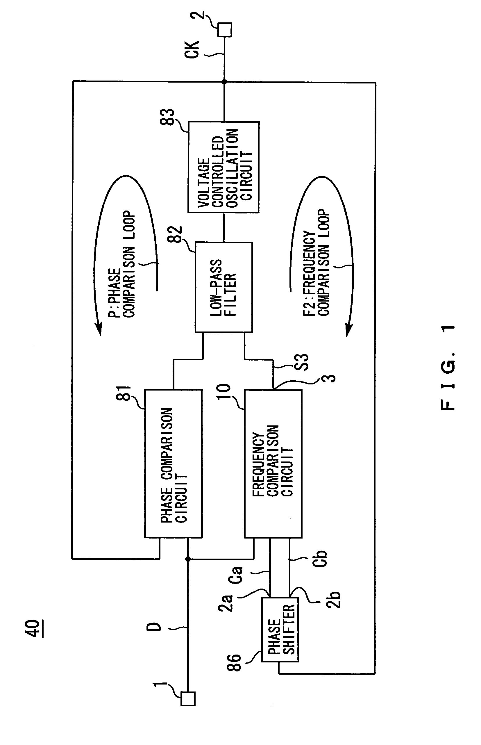
[0013]FIG. 1 is a block diagram of a phase sync circuit in Embodiment 1 of the present invention. In FIG. 1, symbol 40 denotes a phase sync circuit in accordance with the present invention, symbol 1 denotes an input terminal through which a data signal D in a random NRZ format is input; symbol 81 a phase comparison circuit which performs phase comparison between the data signal D input through the input terminal 1 and a signal CK output from a voltage controlled oscillation circuit 83 (described below); symbol 10 a frequency comparison circuit which performs frequency comparison between the data signal D input through the input terminal 1 and a signal Ca output from a terminal 2a of a phase shifter 86 (described below) or a signal Cb output from a terminal 2b of the phase shifter 86, and which produces an output through a terminal 3; symbol 82 a low-pass filter to which both a phase comparison result obtained by the phase comparison circuit 81 and a frequency comp...

embodiment 2

[0047] Embodiment 2

[0048] Embodiment 1 has been described with respect to the operation of the frequency comparison circuit 20 in the phase sync circuit 40 of the present invention. There are some variations of the circuit configuration for realization this operation typified by one in Embodiment 2 described below.

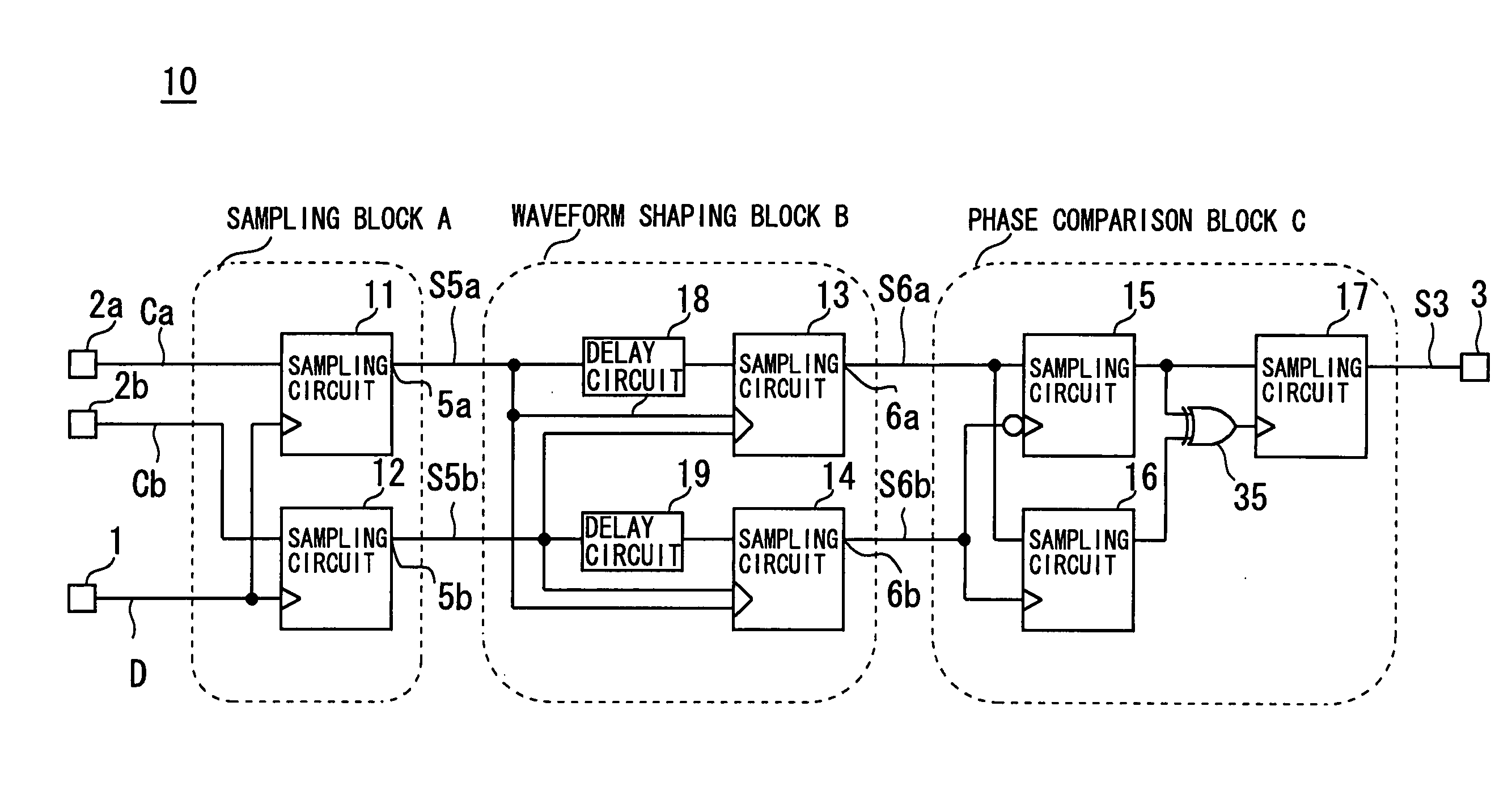
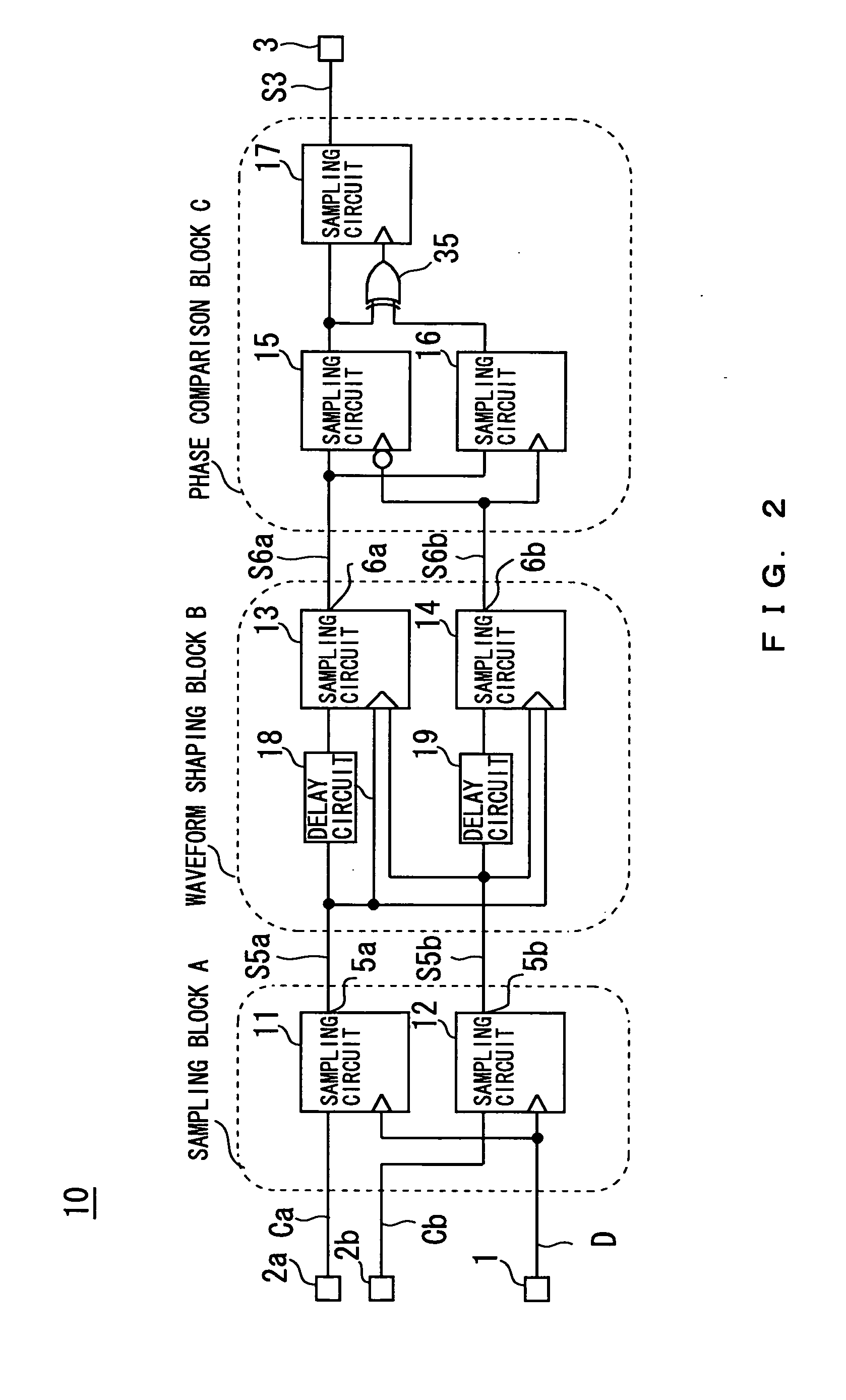
[0049]FIG. 10 shows a circuit forming a sampling block A2 in Embodiment 2 of the present invention. Portions indicated in FIG. 10 by the same symbols as those in FIG. 3 have the same functions. No description will be made of the portions having the same functions. In FIG. 10, symbol 60 denotes another sampling block A2 corresponding to the implementation of the sampling block A, and symbols 61 and 62 denote D flip flop circuits. The sampling block A2 (60) is used instead of the sampling block A in the frequency comparison circuit 20 shown in FIG. 3 to make the minimum value of the pulse width in the signals S5a and S5b appearing at the terminals 5a and 5b about twice the ...

embodiment 3

[0051] Embodiment 3

[0052] As the circuit for implementation of the phase comparison block C in the frequency comparison circuit 20 described above in the description of Embodiment 1, a different circuit such as one in Embodiment 3 may be implemented.

[0053]FIG. 11 shows the circuit in a phase comparison block C2 in Embodiment 3 of the present invention. Portions indicated in FIG. 11 by the same symbols as those in FIG. 3 have the same functions. No description will be made of the portions having the same functions. In FIG. 11, symbol 70 denotes another phase comparison block C2 corresponding to the implementation of the phase comparison block C; symbols 71 to 75 denote D flip flop circuits; symbols 63 to 68 denote AND circuits; symbol 69 denotes an OR circuit; and symbols 94 to 99 denote NOT circuits. The phase comparison block C2 (70) is used instead of the phase comparison block C in the frequency comparison circuit 20 shown in FIG. 3 to improve the accuracy with which verificatio...


PUM


Abstract

In a phase sync circuit (40) which extracts a clock signal CK from a data signal D in a random NRZ format, particularly in a phase sync circuit (40) of a dual loop configuration including both a phase comparison circuit (81) and a frequency comparison circuit (10), a phase sync circuit (40) capable of achieving both broadening of the capture range and extraction of a high-quality clock signal without requiring any reference clock signal is provided. A clock signal Ca, another clock signal Cb having a phase delayed by an approximately ¼ period from the clock signal Ca and the data signal D are input to the frequency comparison circuit (10) to output a logical value according to the high-low relationship between the frequency of the clock signal and the bit rate of the data signal D. This logical value is fed back by a frequency comparison loop F2 to bring the frequency of the clock signal CK close to the bit rate of the data signal D without requiring any reference clock signal, thus achieving both broadening of the capture range and extraction of a high-quality clock signal.

Description

TECHNICAL FIELD [0001] The present invention relates to a phase sync circuit and, more particularly, to a phase sync circuit which extracts a clock signal from a data signal in a random NRZ (non-return-to-zero) format. BACKGROUND ART [0002] It is required that a phase sync circuit used for the purpose of extracting a clock signal from an input data signal in a random NRZ format should continue outputting the clock signal while continuously maintaining the frequency of the clock signal without being influenced by the input data signal. For example, it is required that even in a case where a data signal having a large amount of noise in which pulse fluctuation with respect to time called jitter appears is input, or a case where a data signal such as one having a substantially long consecutive identical digits (CID) is input, the phase sync circuit should continue outputting the clock signal while constantly maintaining the frequency of the clock signal without being influenced by the ...

Claims


Application Information

Patent Timeline
Patent Type & Authority Applications(United States)
IPC IPC(8): H03K5/26H03L7/08H03L7/087H03L7/091H03L7/10H03L7/113H03L7/23H04L7/033
CPCH03L7/087H03L7/091H04L7/033H03L7/235H03L7/113
Inventor TAKEO, YASUHITOTOYODA, NOBUHIROTOBAYASHI, MASATOSHI
Owner NTT ELECTORNICS CORP
Why Eureka
Try Eureka