Environmentally-controlled network interface device and methods

a network interface and environment-controlled technology, applied in the field of telecommunication services, can solve the problems of affecting the operation life of such batteries, affecting the performance and reliability of other electrical and/or optical components, and being prone to degradation

Active Publication Date: 2005-01-13
QWEST
View PDF42 Cites 68 Cited by
  • Summary
  • Abstract
  • Description
  • Claims
  • Application Information

AI Technical Summary

Benefits of technology

[0019] The method, in some cases, may further comprise terminating an external communication medium within the interior space defined by the first and second faces, terminating an internal communication medium within the interior space defined by the first and second faces, and/or providing with at least one telecommunication component communications between the external communication medium and the internal communication medium. In other cases, the method may comprise accessing the interior space of the network interface device from a location external to the subscriber premises (e.g., via the first face of the network interface d

Problems solved by technology

In the past, network interface devices have been fairly unsophisticated, merely providing a hard-wired connection between the premise wiring and the provider network, and have generally been located at the exterior of the subscriber premises, in order to allow the provider's technicians or contractors to access the device for maintenance, upgrade and/or troubleshooting purposes.
Conversely, relatively high temperatures adversely affect the operational life of such batteries.
Likewise, other electrical and/or optical

Method used


Image

  • Environmentally-controlled network interface device and methods
  • Environmentally-controlled network interface device and methods
  • Environmentally-controlled network interface device and methods

Examples


Embodiment Construction

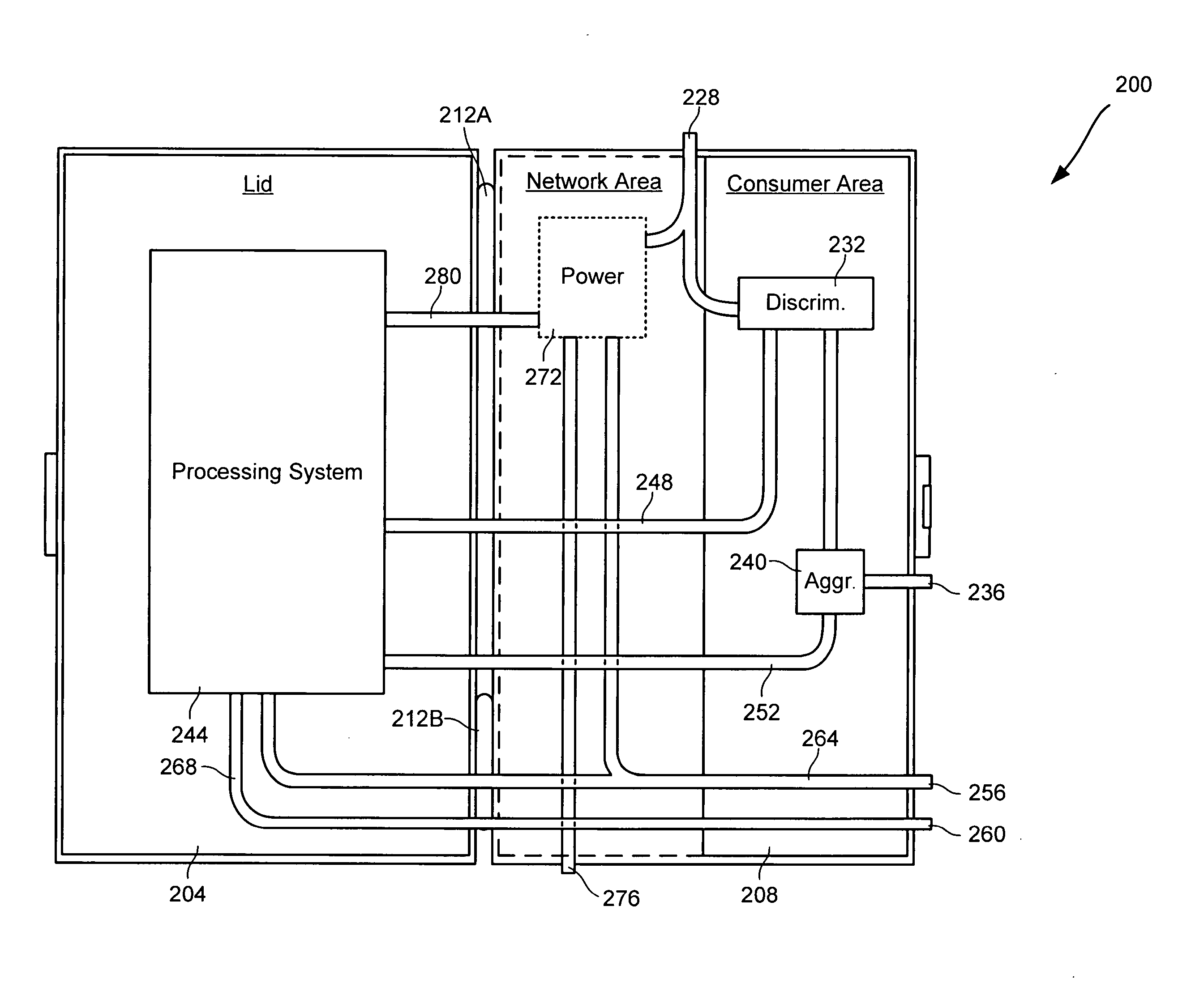
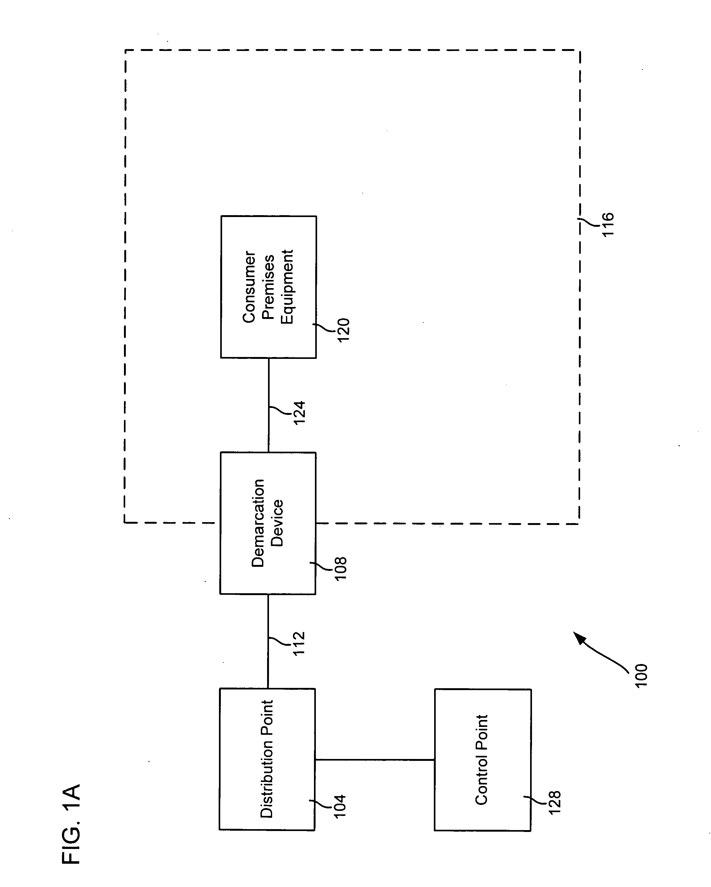
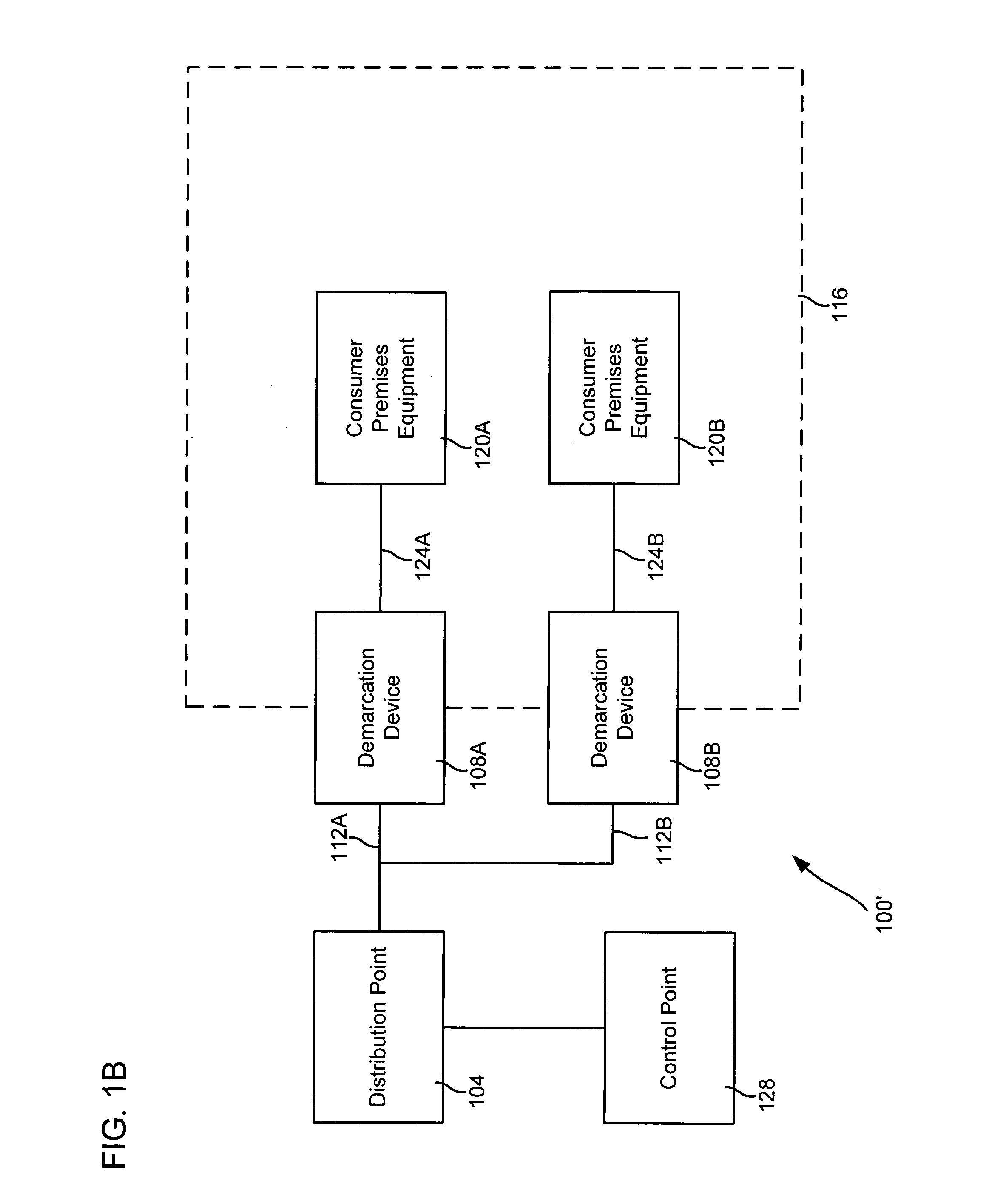
[0034] Certain embodiments of the present invention are directed to demarcation devices that can be used to provide telecommunication services, as well as to methods and systems of using such devices. A demarcation device can be any device capable of serving as an interface between a customer premises and a telecommunication service provider's network. Such devices can include, merely by way of example, set top boxes (which can be used, inter alia, as an interface between a customer's video appliance and a provider's video network), broadband modems (including xDSL modems, cable modems and wireless modems, each of which can be used to provide video and / or data to a customer premises), integrated access devices (which can, for instance, translate between Voice over IP (“VoIP”) signals and traditional telephone signals, thus allowing traditional telephones to connect to a VoIP network), devices compatible with the session initiation protocol (“SIP”) familiar to those skilled in the ar...


PUM


Abstract

Certain embodiments of the invention provide network interface devices, as well as systems and methods for using them. In accordance with some embodiments, a network interface device may provide a controlled environment for an interior space defined by the exterior of network interface device. The network interface device may further be configured to be exposed to an interior of a subscriber premises and/or to allow for thermal transfer between the interior of the subscriber premises and the interior of the network interface device. In particular embodiments, the network interface device may be configured to be disposed at least partially within an external wall of the subscriber premises. In some cases, a portion of the network interface device exposed to the exterior of the subscriber premises may be insulated and/or one or more openings may be provided in the portion of the network interface device exposed to the interior of the subscriber premises, which can allow air to circulate between the interior of the subscriber premises and the interior of the network interface device.

Description

CROSS-REFERENCES TO RELATED APPLICATIONS [0001] This application is a continuation-in-part of U.S. application Ser. No. 10 / 356,364, filed Jan. 31, 2003 by Phillips et al. and entitled “Packet Network Interface Device and Systems and Methods for Its Use” (the “364 Application”), the entire disclosure of which is hereby incorporated by reference for all purposes.BACKGROUND [0002] The present invention relates to the provision of telecommunication services. [0003] Those skilled in the art will recognize that telecommunication service providers often employ a network interface device or other demarcation device at a subscriber premises. The network interface device generally is designed to serve as an interface between the customer's premise wiring (or other local communications media) and the provider's network. In the past, network interface devices have been fairly unsophisticated, merely providing a hard-wired connection between the premise wiring and the provider network, and have ...

Claims


Application Information

Patent Timeline
IPC IPC(8): G08B27/00H04L12/58H04L29/06H04N5/445H04N5/45H04N7/14H04N7/16H04N7/173H04N7/24
CPCG08B27/005H04L65/80H04N5/44513H04N5/45H04N7/108H04N7/141H04N21/234363H04N21/235H04N21/4122H04N21/4223H04N21/4316H04N21/435H04N21/43632H04N21/4622H04N21/4782H04N21/4886H04N21/6377H04N21/658H04N21/6587H04N2007/1739H04L12/58H04M11/00H04L51/00H04M11/002H04M11/062H04N21/47
Inventor COOK, CHARLES I.
Owner QWEST
Why Eureka
Try Eureka