Optical waveguide amplifier

a technology of optical waveguide amplifier and amplifier, applied in the direction of optical waveguide light guide, optical light guide, instruments, etc., can solve the problem of low gain dynamic rang

Inactive Publication Date: 2005-01-13
PHOTON
View PDF6 Cites 10 Cited by
  • Summary
  • Abstract
  • Description
  • Claims
  • Application Information

AI Technical Summary

Problems solved by technology

However, because the material and waveguide properties of conventional waveguide amplifiers are constant throughout the medium, conventional waveguide amplifiers are suitable for only a limited range of input signal power values.
This results in low gain dynamic range.

Method used


Image

  • Optical waveguide amplifier
  • Optical waveguide amplifier
  • Optical waveguide amplifier

Examples


Embodiment Construction

[0029] In the following description, reference is made to the accompanying drawings that form a part thereof, and in which is shown by way of illustration a specific exemplary embodiment in which the invention may be practiced. This embodiment is described in sufficient detail to enable those skilled in the art to practice the invention and it is to be understood that other embodiments may be utilized and that changes may be made without departing from the scope of the present invention. The following description is, therefore, not to be taken in a limited sense.

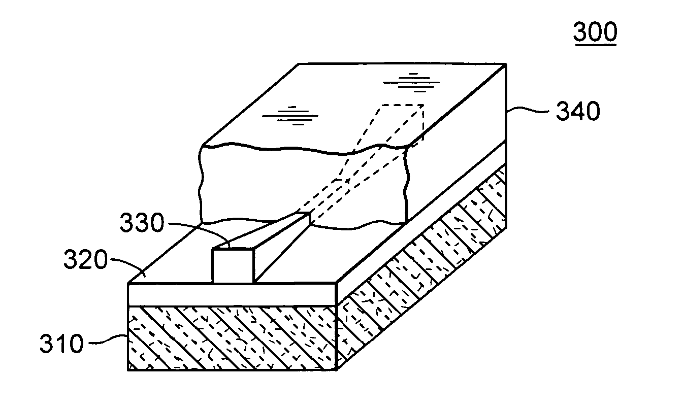
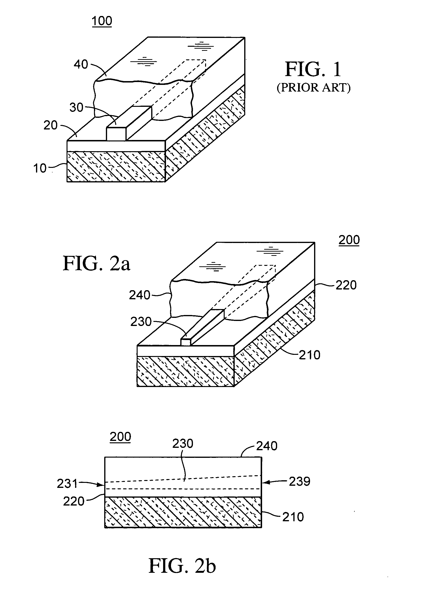
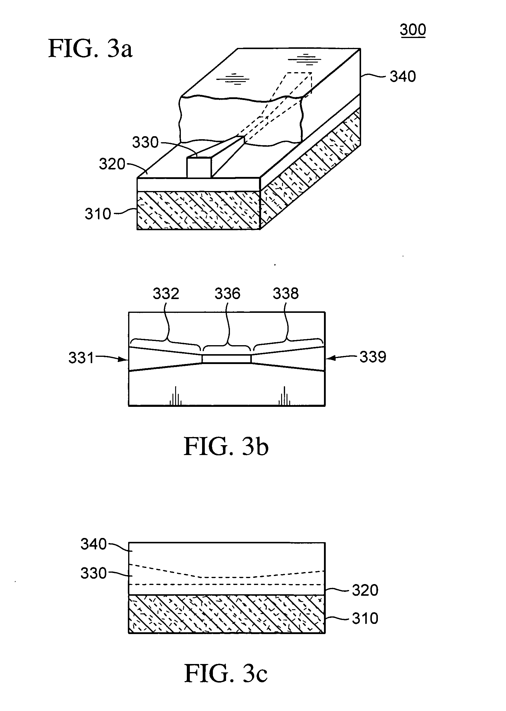
[0030]FIGS. 2-8 disclose waveguide amplifier structures, methods of use, and methods of manufacture, in accordance with an exemplary embodiment of the present invention. The exemplary waveguide amplifier structures can propagate an input optical signal. Further, the exemplary waveguide amplifiers can amplify the input optical signal in a range of mode-field regions. The amplification can enhance performance in both small si...


PUM


Abstract

Waveguide amplifiers having high gain dynamical range, methods for amplifying optical signals, and methods for fabricating wave guide amplifiers are provided. The waveguide amplifiers include a substrate, lower cladding, upper cladding, and a core having a varying cross-section.

Description

CROSS-REFERENCE TO RELATED APPLICATIONS [0001] The present application claims the benefit of U.S. Provisional Patent Application Ser. No. 60 / 467,143 filed May 2, 2003, and is incorporated by reference in its entirety herein.TECHNICAL FIELD [0002] The invention generally relates to optical amplifiers, and more particularly, to optical waveguide amplifier configurations having high gain dynamical range. BACKGROUND [0003] Optical waveguide amplifiers have been attracting great interest because of their promising integration capability with other passive and active optical components. Further, waveguide amplifiers can be realized at a low cost, be multi-functional, and be combined with advanced integrated light circuits. A conventional waveguide amplifier 100, shown in FIG. 1, includes a substrate 10, a lower cladding layer 20, a core 30, and an upper cladding layer 40. In conventional waveguide amplifier 100, the cross-section of core 30 and the numerical aperture (NA) are constant. [0...

Claims


Application Information

Patent Timeline
Patent Type & Authority Applications(United States)
IPC IPC(8): G02B6/122G02B6/138G02B6/30
CPCG02B6/1228G02B6/305G02B6/138
Inventor YENIAY, AYDIN
Owner PHOTON
Why Eureka
Try Eureka