Antiwear device for a variable pitch system for a turbomachine vane

a technology of variable pitch and anti-wear device, which is applied in the direction of rotors, vessel parts, vessel construction, etc., can solve the problems of contacting surfaces, affecting the general operation of the device, and affecting the service life of the device, so as to avoid damage

Inactive Publication Date: 2005-01-13
SNECMA MOTEURS SA
View PDF8 Cites 27 Cited by
  • Summary
  • Abstract
  • Description
  • Claims
  • Application Information

AI Technical Summary

Benefits of technology

[0008] An object of the invention is to avoid the damage due to wear phenomena at the hinge of the vane pivot in prior art devices by proposing a variable pitch vane control device capable

Problems solved by technology

Nevertheless, in certain extreme conditions of use that depend on operating temperature, on contact pressure, on movement amplitude, or indeed on the environment, the stresses on the hinges expose the contacting surfaces to wear-type degradation that can s

Method used


Image

  • Antiwear device for a variable pitch system for a turbomachine vane
  • Antiwear device for a variable pitch system for a turbomachine vane

Examples


Embodiment Construction

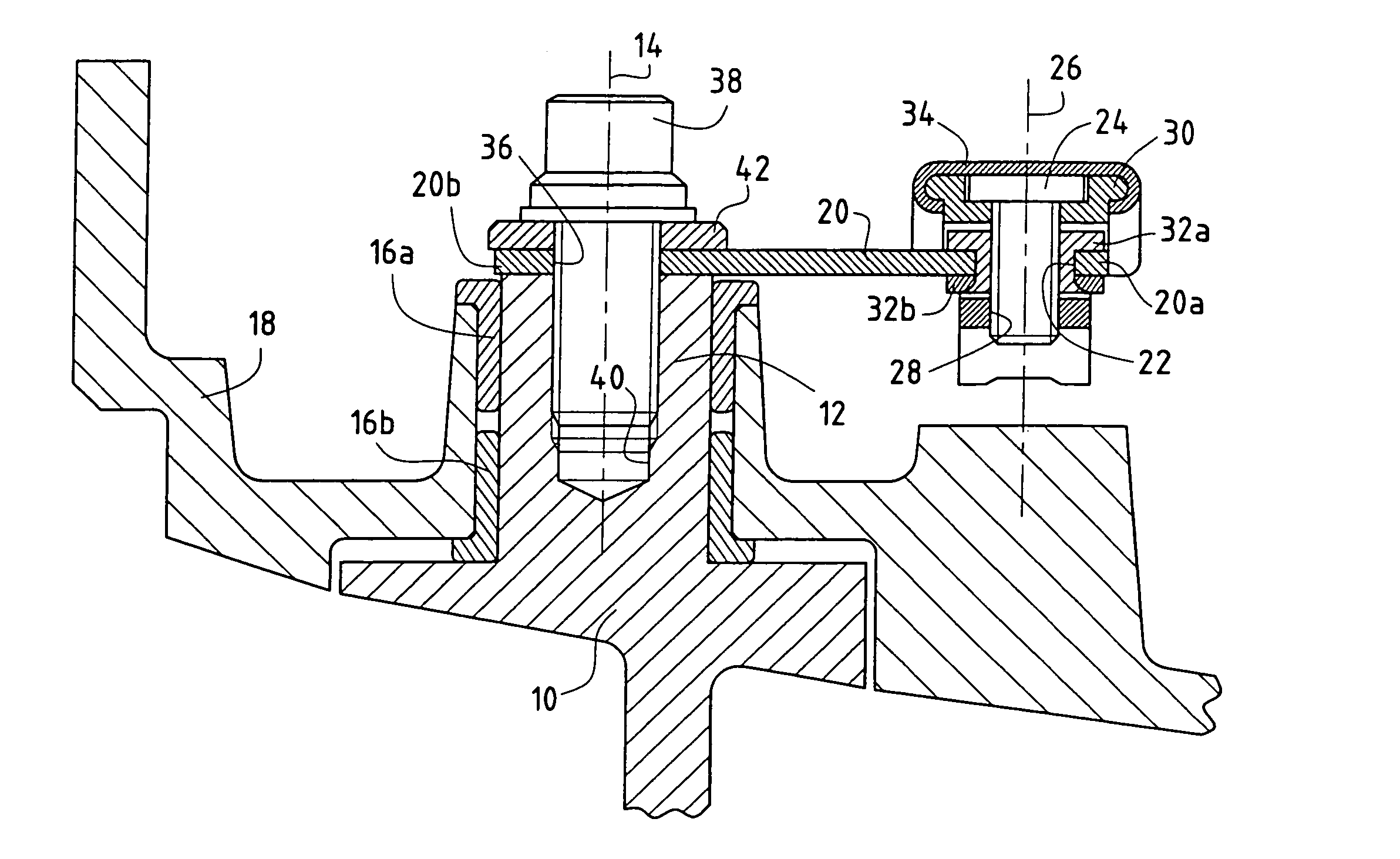
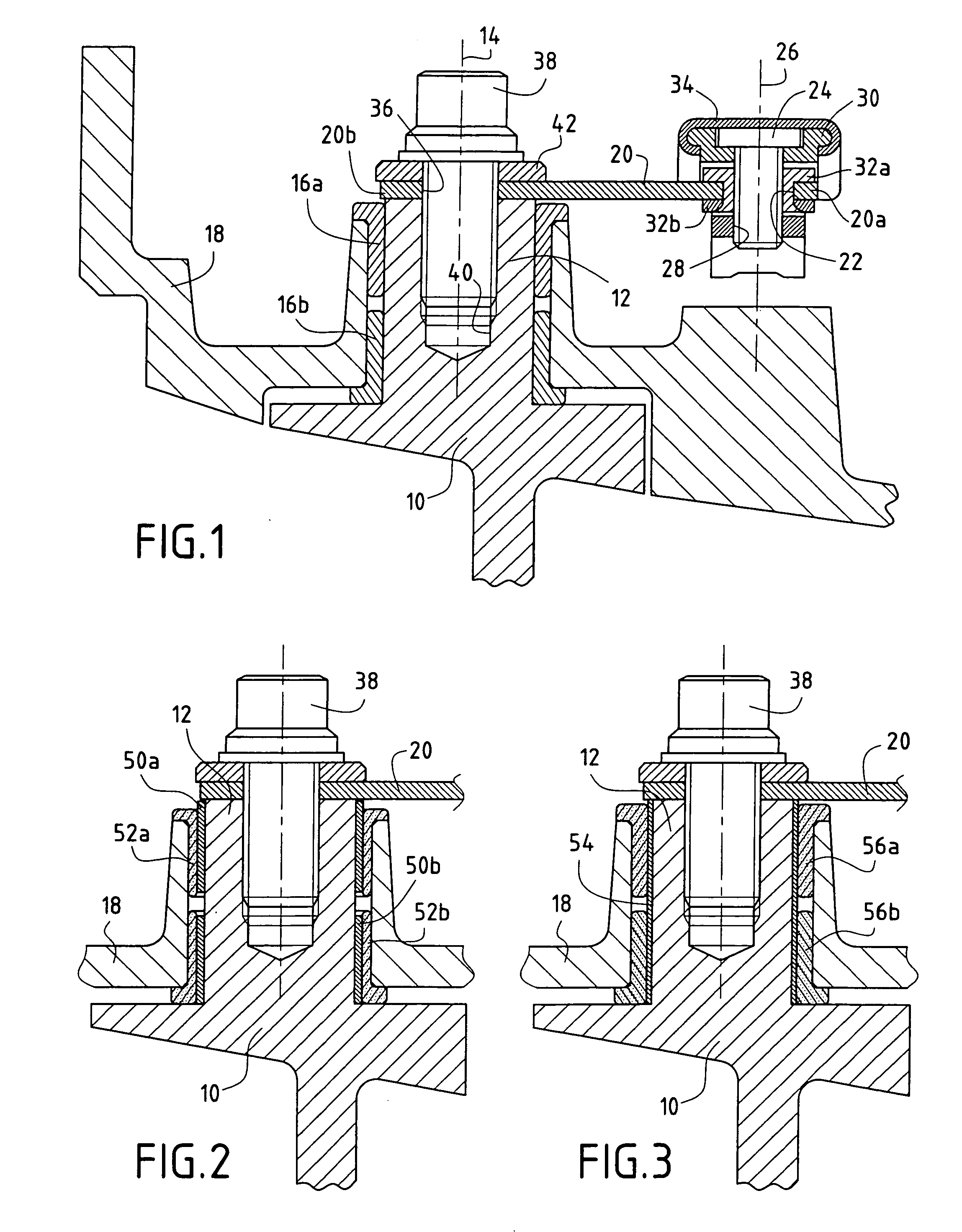
[0018]FIG. 1 is a section view through a portion of a turbomachine, a turbojet or a turboprop for aircraft or any other land-based or sea-based generator, showing by way of example one of the variable pitch guide vanes 10 that are distributed around the axis of such a machine and that are located at the inlet to its compressor.

[0019] Each vane 10 is provided with a vane pivot 12 of axis 14 capable of turning inside a smooth bearing defined by a two-part ring 16a, 16b passing through a portion of the body 18 of the turbomachine (specifically an outer shroud or the stator casing).

[0020] The angular position (pitch) of each vane 10 is varied by a flexible link 20 preferably comprising a flexible composite structure such as a laminated structure constituted by thin layers of metal alternating with layers of elastomer, the layers being bonded to one another as taught in above-cited French patent application No. 2 814 206. The metal layers are formed by sheets of metal of thickness that...


PUM

PropertyMeasurementUnit
Fractionaaaaaaaaaa
Fractionaaaaaaaaaa
Fractionaaaaaaaaaa

Abstract

A flexible link is hinged at a first end to a control ring and is fixed at a second end to a pivot for a vane that is to be controlled that is capable of turning in a smooth bearing passing through a portion of the body of a turbomachine. An insert ring constituted by a nickel- or cobalt-based metal material is interference fitted on the vane pivot, and the smooth bearing is made of a ceramic material.

Description

FIELD OF THE INVENTION [0001] The present invention relates to controlling vanes having a variable pitch angle. The invention finds in particular an application in the field of aviation, in particular for controlling the angular positions of air inlet guide vanes in the compressors of turbomachines, such as turbojets or turboprops for aircraft. BACKGROUND OF THE INVENTION [0002] Known devices for controlling variable pitch vanes in a turbomachine usually comprise a control member in the form of a ring surrounding a casing of the turbomachine together with a plurality of levers or links, each link having a first end connected to the control ring by a hinge and a second end mounted on a pivot of a corresponding vane. [0003] The angular positions of all of the vanes are modified synchronously by turning the ring about the axis of the turbomachine. In order to be able to follow the turning movement of the ring, the connection between each link and the ring includes at least one degree o...

Claims


Application Information

Patent Timeline
IPC IPC(8): F02C1/00F01D17/16F04D29/02F04D29/56
CPCF01D17/16F01D17/162Y02T50/672F04D29/023F04D29/563F01D17/165F05D2230/64F05D2300/17F05D2300/2112Y02T50/60
Inventor PERRUCHAUT, PHILIPPEPIEKOSZ, CHRISTIAN
Owner SNECMA MOTEURS SA
Why Eureka
Try Eureka