
Sensor informationlinkage apparatus

Inactive Publication Date: 2005-01-13
PANASONIC CORP +1
View PDF3 Cites 21 Cited by
  • Summary
  • Abstract
  • Description
  • Claims
  • Application Information

AI Technical Summary

Benefits of technology

[0005] In view of the above, an objective of the present invention is to readily obtain a detection result for a detection target which is difficult to detect with a single device, such that the operation control of the device is performed more appropriately, and various operation control are performed.
[0020] With the above structures, even if the power of the sensor information association device is off at a time when a detection result is obtained by a device having a sensor, the detection result can be obtained at a timing when the sensor information association device performs operation control. Furthermore, in the case where the detection result of the sensor is not utilized, the load of transmitting the detection result in vain is reduced.

Problems solved by technology

However, in some cases, a detection target for performing optimum control is not necessarily readily detected.
However, it is not realistic when the arrangement of wires, or the like, is considered.
That is, even if the detected temperature is transmitted among the controllers, it is impossible to make what cannot be detected by the system detectable.

Method used


Image

  • Sensor informationlinkage apparatus
  • Sensor informationlinkage apparatus
  • Sensor informationlinkage apparatus

Examples


embodiment 1

[0039] (Embodiment 1)

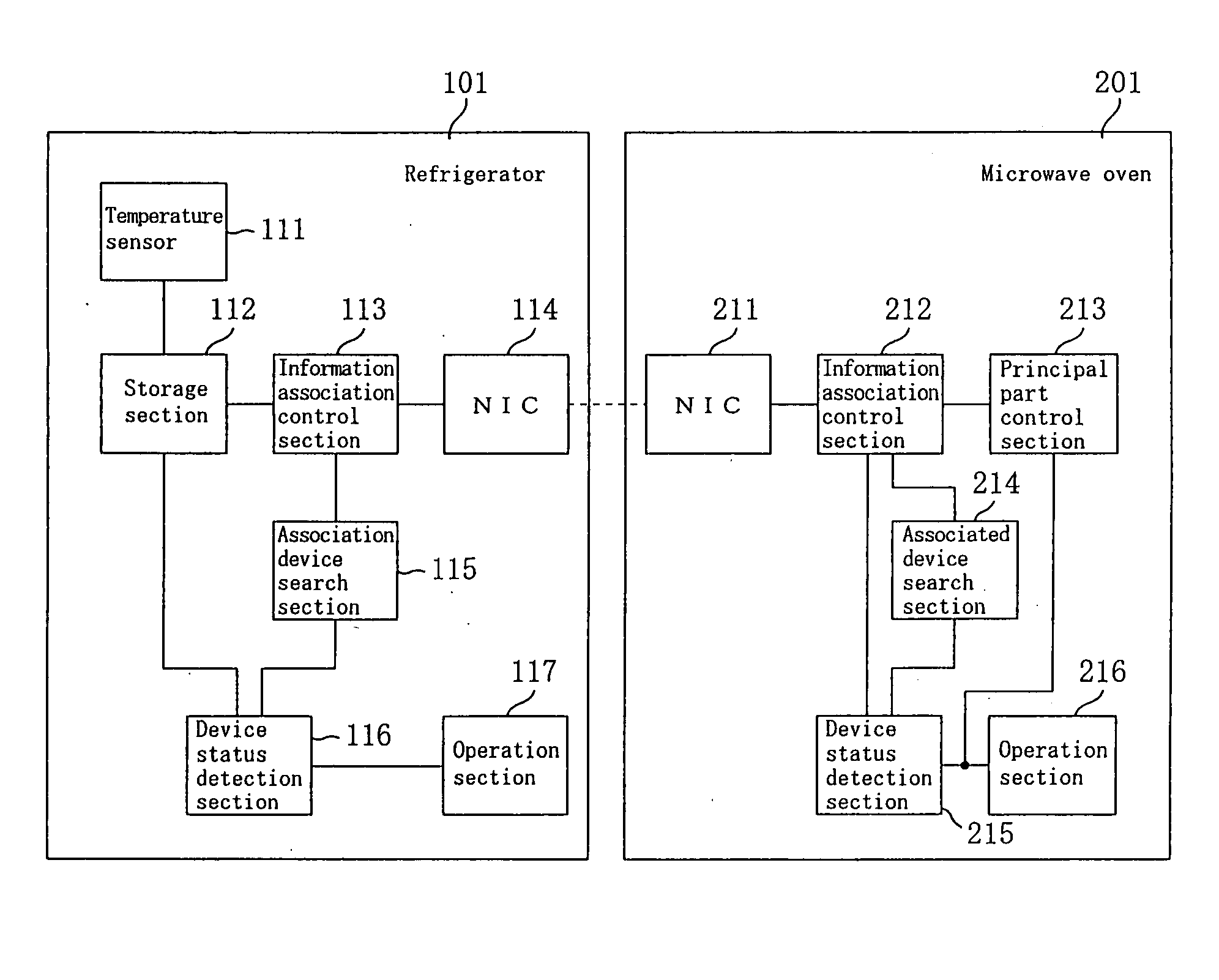
[0040] Hereinafter, an example of embodiment 1 of the present invention is described, wherein a refrigerator and a microwave oven, which are sensor information association devices, are associated with each other, and a detection result of the temperature inside the refrigerator is utilized such that the microwave oven performs an appropriate heating operation.

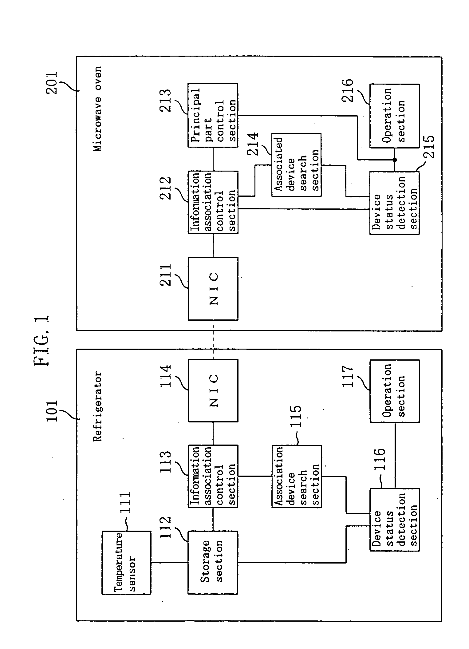
[0041]FIG. 1 is a block diagram showing the structure of principal part of a refrigerator 101 and a microwave oven 201 according to embodiment 1 of the present invention.

[0042] In FIG. 1, a temperature sensor 111 detects the compartment temperature of the refrigerator 101. In the case where the refrigerator 101 has a freezer compartment, a chilled compartment, and the like, the temperature sensor 111 is preferably provided to each compartment.

[0043] A storage section 112 stores a detection result obtained by the temperature sensor 111. For example, at the time when a material to be cooked is taken out of...

embodiment 2

[0066] (Embodiment 2)

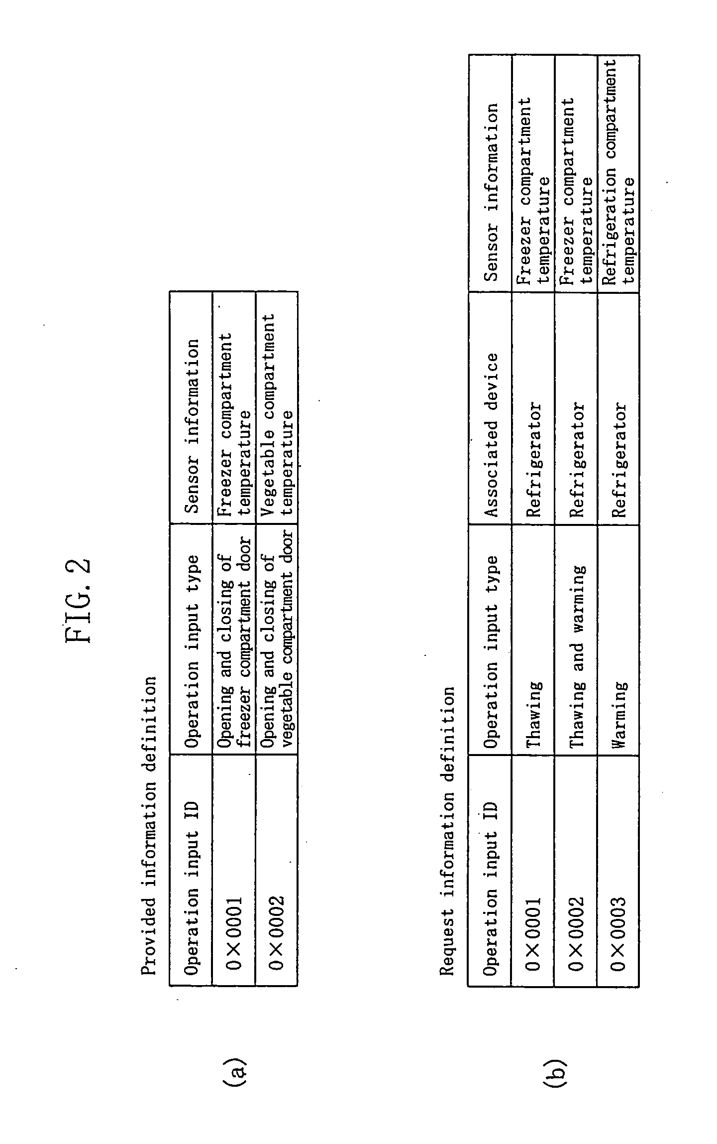
[0067] In an example described herein, when a user performs any operation at the microwave oven 201, a device with which a detection result of a sensor is associated is searched for. In embodiment 2, the structure of the refrigerator 101 and the microwave oven 201 is basically the same as that of embodiment 1 (FIG. 1) except for a control operation performed by the information association control section 113 and the information association control section 212. Further, the request information definition stored in the information association control section 212 of the microwave oven 201 includes, in addition to the information shown in FIG. 2(b), information that indicates the timing of searching for an associable device, e.g., information indicating that the search is performed when the door of the microwave oven 201 is opened.

[0068] As shown in FIG. 4, the refrigerator 101 determines whether or not a user has performed an operation at the operation section 117...


PUM


Abstract

For the purpose of associating a device having a sensor with a device which utilizes a detection result so as to enable various operation control, a refrigerator includes a temperature sensor for detecting a compartment temperature, a storage section for storing a detection result, an information association control section for controlling transmission of the detection result to a microwave oven, and the like, and an NIC for communicating with the microwave oven through a network, or the like. The microwave oven includes an NIC of the same type, an information association control section for controlling reception of the compartment temperature transmitted from the refrigerator, and the like, and a principal part control section for controlling the operation of principal part of the microwave oven. The microwave oven heats food taken out of the refrigerator by performing heating control according to the compartment temperature at the time when the food is taken out of the refrigerator, i.e., the core temperature of the food.

Description

TECHNICAL FIELD [0001] The present invention relates to a device which performs control based on detection with a sensor, such as a heating cooking appliance in which the heating power is controlled according to the temperature of a material to be cooked, a cloth dryer in which the degree of heating is controlled according to the ambient temperature. Specifically, the present invention relates to a sensor information association device capable of effectively using a detection result obtained by a sensor among a plurality of devices. BACKGROUND ART [0002] For example, in many household electric appliances, or the like, the operation of the appliance is controlled according to the outputs of various sensors. Specifically, in a microwave oven, the temperature at the surface of a material to be cooked is detected to control the heating power. In the case of a cloth dryer, the temperature inside the dryer is detected to control the degree of heating. [0003] However, in some cases, a dete...

Claims


Application Information

Patent Timeline
IPC IPC(8): G05B19/042
CPCG05B19/0421G05B2219/21014G05B2219/2654G05B2219/25234G05B2219/2643G05B2219/2213
Inventor MATSUURA, SATOSHINAKAMURA, ATSUSHIHATTORI, ATSUSHIINAGAWA, TOMOHIROKASHIMOTO, TAKASHIOGAWA, KEIJI
Owner PANASONIC CORP
Learn More