Safety controller and system using same

a safety controller and controller technology, applied in the field of safety controllers and systems, can solve the problems of increasing the number of wires, complicated systems, and difficulty in designing such systems, and achieve the effects of easy expansion, simplified wiring, and easy change of a portion

Active Publication Date: 2005-01-13
ORMON CORP
View PDF38 Cites 34 Cited by
  • Summary
  • Abstract
  • Description
  • Claims
  • Application Information

AI Technical Summary

Benefits of technology

[0023] A system according to this invention is characterized as comprising a plurality of safety controllers according to this invention connected together through the connecting output parts and through the connecting input parts. With a system thus structured, safety circuits need not be formed by relay sequence unlike with a relay unit of a prior art type comp

Problems solved by technology

In a system using a relay unit containing such electromagnetic relays, a logic is formed by wiring because the safety circuit is formed by the relay sequence and if there are many fabrication machines or the like to be controlled, the number of wires increases, the system becomes complicated and it becomes difficult to design such a system.
When it becomes desirable to modify a portion of a system in response to the use

Method used


Image

  • Safety controller and system using same
  • Safety controller and system using same
  • Safety controller and system using same

Examples


Embodiment Construction

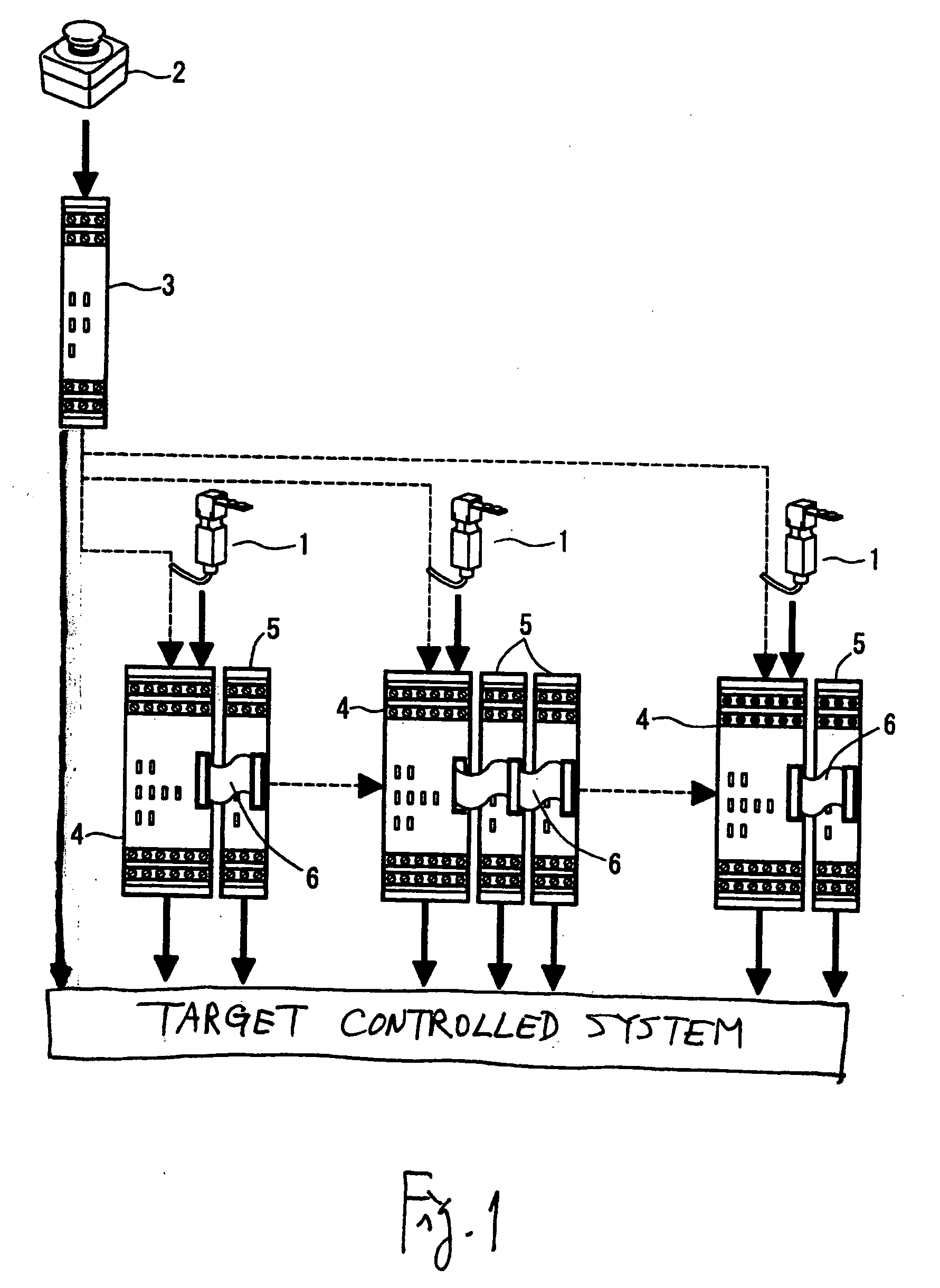
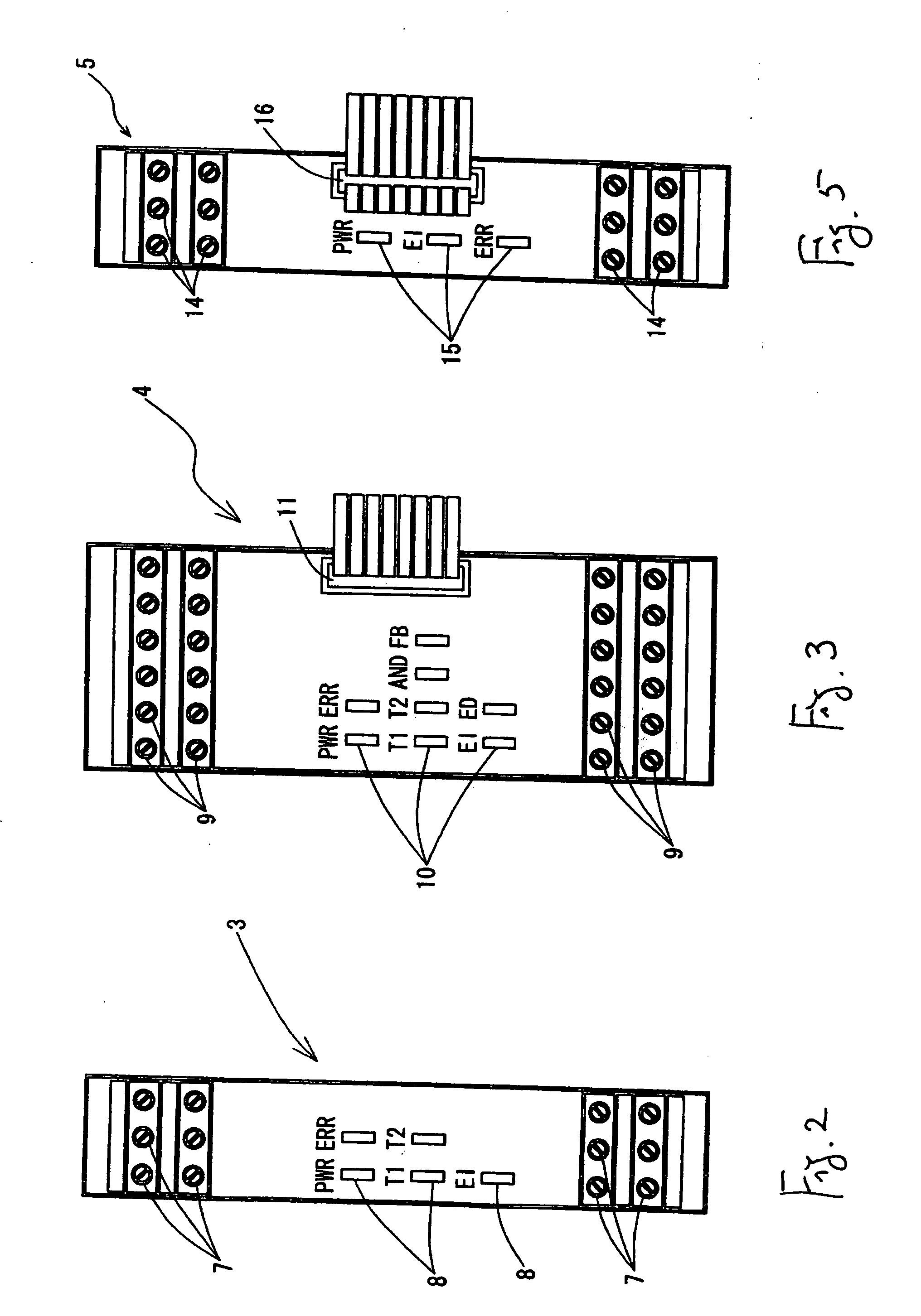
[0044] The invention is described next in detail with reference to drawings. FIG. 1 shows the structure of an example of a system using safety controllers embodying this invention. The safety controllers according to this embodiment are a safety circuit for supplying electric power to a machine equipment such as fabrication machines or industrial robots (not shown) only when safety is assured. There are three kinds of safety controllers shown in this example, a basic unit 3 connected to an input device such as an emergency stop switch 2, advanced units 4 each connected to the basic unit 3 and also to an input device such as a safety door switch 1, and expansion units 5 each connected to one of these advanced units 4 through a cable 6.

[0045] The basic unit 3 serves not only to receive inputs from input devices such as the emergency stop switch 2 but also to output safety output signals to a magnet contactor or the like as a target of control by supplying and shutting off power to a ...


PUM


Abstract

A safety controller provides a safety output to a target controlled system such as a magnet contactor based on an input from an input device such as a safety door switch to thereby control operation of machine equipment. Safety output parts serve to transmit a solid-state output as the safety output and a connection output part transmits a connection output to another safety controller. A control part having two CPUs controls the safety output and the connection output according to a program based on the input from the input device. Two or more of such safety controllers are connected through their connecting output parts and the connecting input parts to together form a safety system.

Description

[0001] Priority is claimed on Japanese Patent Applications 2003-193359 filed Jul. 8, 2003 and 2003-394386 filed Nov. 25, 2003. BACKGROUND OF THE INVENTION [0002] This invention relates to a safety controller and a system using such a safety controller. In particular, this invention relates to a safety controller of the kind suitable for a safety circuit for a machine equipment such as fabrication machines and industrial robots and a system using such a safety controller. [0003] Japanese Patent Publication Tokkai 2003-14072, for example, disclosed a safety circuit using a relay unit containing a plurality of electromagnetic relays for securing labor safety at a production site, adapted to supply electric power to a machine equipment such as fabrication machines and industrial robots only when their safe condition is assured. Such a relay unit serves to monitor the condition of a safety circuit on the basis of an input signal from a safety switch such as an emergency stop switch or a ...

Claims


Application Information

Patent Timeline
IPC IPC(8): G05B19/048G05B9/03G05B19/042
CPCG05B19/0428G05B9/03G05B19/048
Inventor ABE, YUICHINAKAYAMA, TERUYUKIHASHIMOTO, YUJIHASHIMOTO, MINORUIDE, TAKAHIRO
Owner ORMON CORP
Why Eureka
Try Eureka