
Computer apparatus and method for autonomically detecting system reconfiguration and maintaining persistent I/O bus numbering

Inactive Publication Date: 2005-01-13
IBM CORP
View PDF4 Cites 1 Cited by
  • Summary
  • Abstract
  • Description
  • Claims
  • Application Information

AI Technical Summary

Benefits of technology

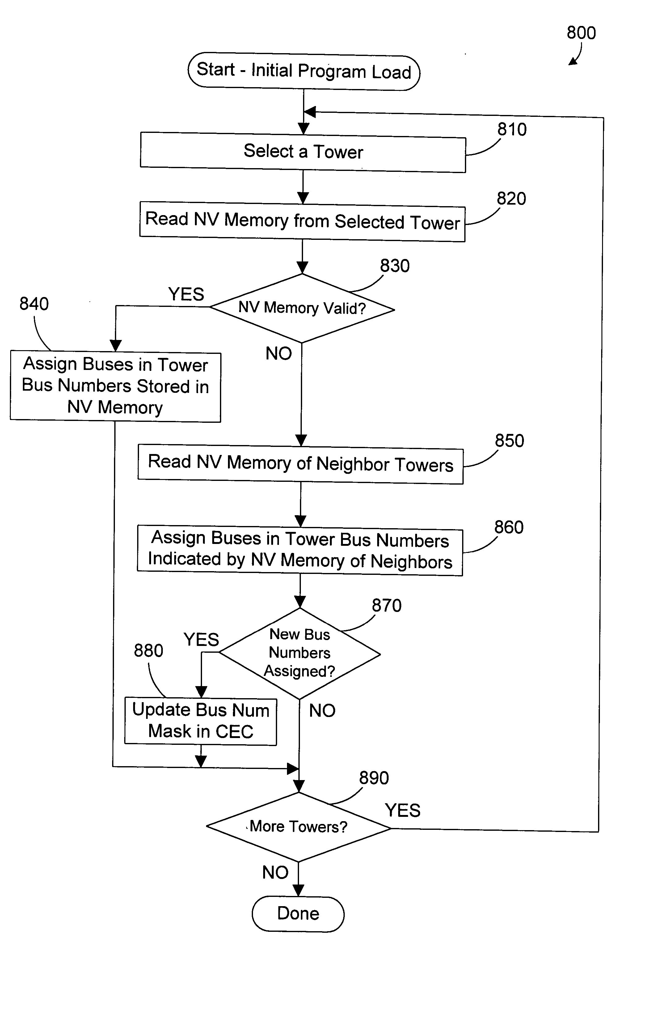
[0008] In a computer system that includes multiple physical enclosures, an enclosure includes a non-volatile memory that includes bus numbering information for its own buses as well as bus numbering information for one or more of its neighbors. In the preferred implementation, all enclosures include a non-volatile memory that includes bus numbering information for its own buses and for both of its neighbors. This creates a distributed database of the interconnection topology for the computer system. Because an enclosure contains bus num

Problems solved by technology

The prior art method 400 has thus produced two undesirable results of the upgrade to Tower C 140.
This is a time-consuming process that must be performed by a highly-skilled system administrator.
Note, however, that some system reconfigurations may occur as hardware fails, or as towers are rearranged in different connection topologies or orders.
To address these unpredictable cases, a skilled system administrator would have to be available at all times. This is a costly and undesirable solution.
A second undesirable result is that bus numbers 7, 8 and 9 that were used in Tower C 140 before the upgrade are no longer available for use.
As a result, over time, there may be a relatively large number of bus numbers that are unavailable for use.

Method used


Image

  • Computer apparatus and method for autonomically detecting system reconfiguration and maintaining persistent I/O bus numbering
  • Computer apparatus and method for autonomically detecting system reconfiguration and maintaining persistent I/O bus numbering
  • Computer apparatus and method for autonomically detecting system reconfiguration and maintaining persistent I/O bus numbering

Examples


Embodiment Construction

1. OVERVIEW OF PRIOR ART

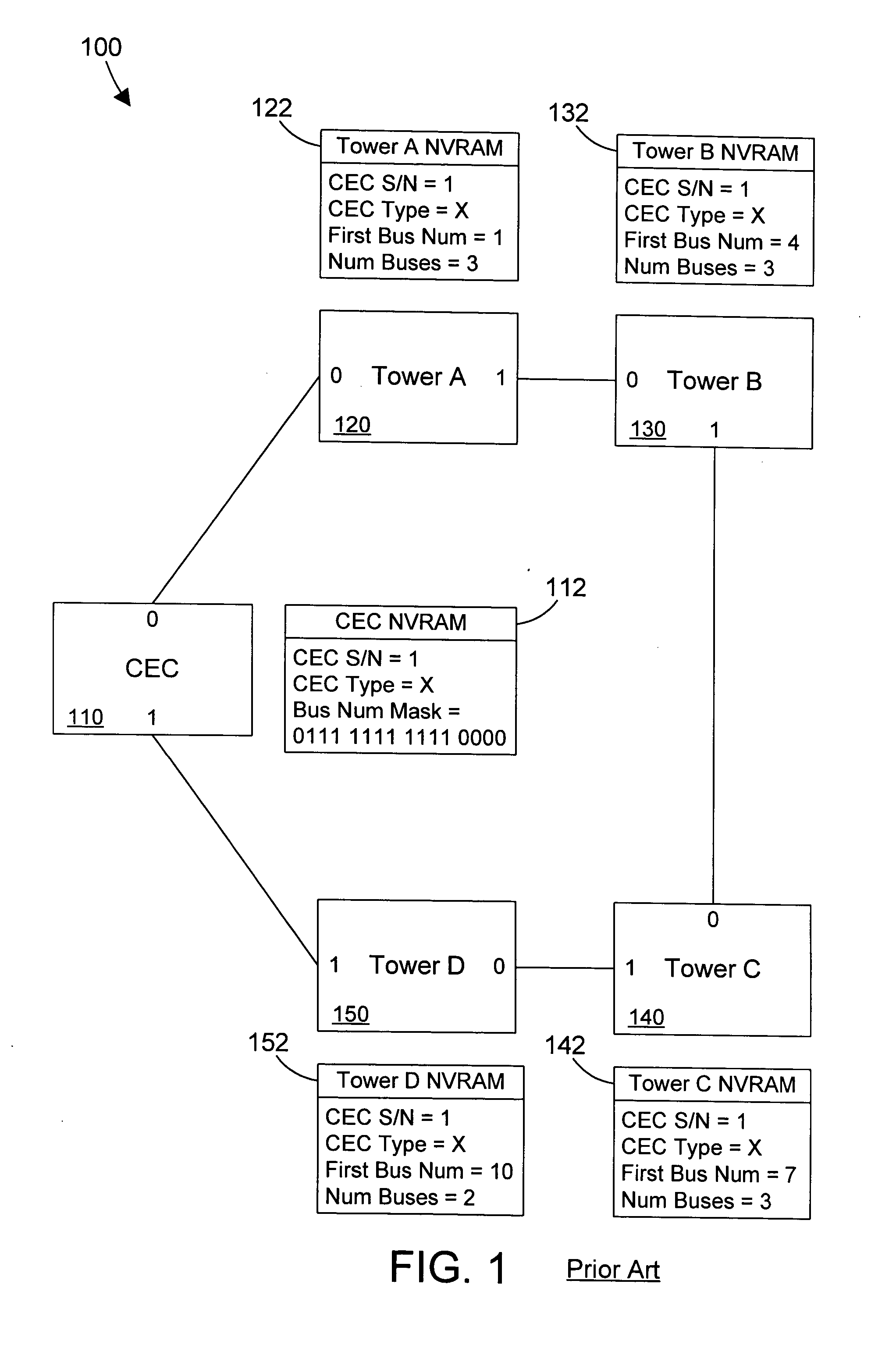
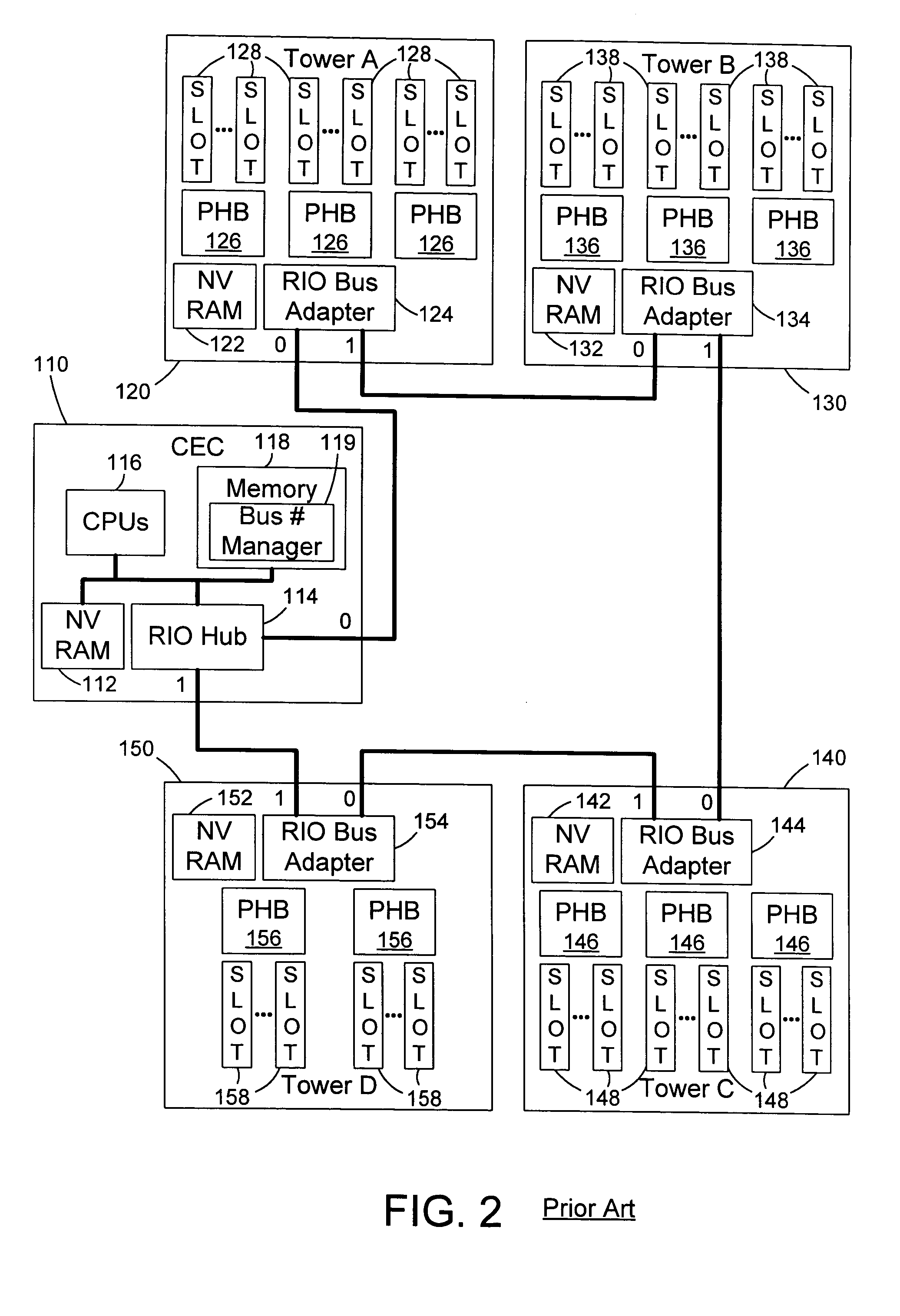
[0019] An understanding of the prior art helps to more fully understand the preferred embodiments of the present invention. FIG. 1 shows a sample prior art computer system 100 that includes a central electronics complex (CEC) 110 and four I / O towers 120, 130, 140 and 150. The CEC 110 includes two ports labeled 0 and 1 for connection to I / O towers. In similar fashion, each I / O tower includes two ports labeled 0 and 1 for connection to the CEC and / or other I / O towers. In the specific configuration shown in FIG. 1, the CEC 110 and four towers 120, 130, 140 and 150 are arranged in a loop configuration.

[0020] Each I / O tower includes a non-volatile memory. Non-volatile Random Access Memories (NVRAMs) are shown in FIG. 1 as one specific type of non-volatile memory that could be used. Tower A 120 contains NVRAM 122; Tower B 130 contains NVRAM 132; Tower C 140 contains NVRAM 142; and Tower D 150 contains NVRAM 152. Each tower NVRAM contains the serial number of the ...


PUM


Abstract

In a computer system that includes multiple physical enclosures, an enclosure includes a non-volatile memory that includes bus numbering information for its own buses as well as bus numbering information for one or more of its neighbors. In the preferred implementation, all enclosures include a non-volatile memory that includes bus numbering information for its own buses and for both of its neighbors. This creates a distributed database of the interconnection topology for the computer system. Because an enclosure contains bus numbering information about its neighbor enclosure(s), the bus numbers for the buses in the physical enclosures are made persistent across numerous different system reconfigurations. The preferred embodiments also include a bus number manager that reads the non-volatile memories in the physical enclosures during initial program load (i.e., boot) that reconstructs the interconnection topology from the information read from the non-volatile memories, and that assigns bus numbers to the buses according to the derived interconnection topology.

Description

BACKGROUND OF THE INVENTION [0001] 1. Technical Field [0002] This invention generally relates to data processing, and more specifically relates to the assignment of bus numbers in a computer system that has multiple buses in multiple physical enclosures. [0003] 2. Background Art [0004] Since the dawn of the computer age, computer systems have evolved into extremely sophisticated devices that may be found in many different settings. Computer systems typically include a combination of hardware (e.g., semiconductors, circuit boards, etc.) and software (e.g., computer programs). As advances in semiconductor processing and computer architecture push the performance of the computer hardware higher, more sophisticated computer software has evolved to take advantage of the higher performance of the hardware, resulting in computer systems today that are much more powerful than just a few years ago. [0005] Large computer systems typically include several different physical enclosures. For exa...

Claims


Application Information

Patent Timeline
IPC IPC(8): G06F13/00G06F13/40
CPCG06F13/4081
Inventor BAILEY, DAVID ALANNORDSTROM, GREGORY MICHAELSAND, THOMAS REMBERT
Owner IBM CORP
Learn More