Al technical title is built by PatSnap Al team. It summarizes the technical point description of the patent document.
a technology of access control and access control, applied in the field of security, can solve the problems of not being able to prevent terminated employees from accessing all corporate data still stored on their laptops or home computers, and often left with no features, etc., to save significantly over the cost of a traditional large-scale security system, and achieve massive scalability. , the effect of easy recovery
Inactive Publication Date: 2005-01-13
ASSA ABLOY AB
View PDF98 Cites 57 Cited by
Summary
Abstract
Description
Claims
Application Information
AI Technical Summary
This helps you quickly interpret patents by identifying the three key elements:
Problems solved by technology
Method used
Benefits of technology
[0010] The present invention provides a solution that virtually guarantees that access to all corporate computers (office, remote and even disconnected laptops) be limited to currently authorized employees. A terminated employee will be unable to log in to his or her computer either immediately or within hours of losing authorization—even if that laptop is kept at home and not connected to the network. The added security can be made completely invisible to legitimate users. The present invention may provide seamless integration with existing Windows login management infrastructure and may be invisible to end users under normal operation. Access revocation to a particular computer may not require any network connection works with all disconnected computers. An administrator may set scheduled access rights by user or group. The present invention may provide easy recovery from inadvertent shut-outs.
[0011] The present invention provides massive scalability (on the order of hundreds of millions or more users). The present invention does not require secure distributed servers (since the issued proofs can be stored and distributed to unsecured computers), which can save significantly over the costs of a traditional large-scale security system. The present invention provides fast response time on average because the validation operation takes no time at log-in when the proofs are already stored locally and because retrieving a proof from the network is a sub-second operation almost everywhere in the world. The present invention also provides for minimal connectivity requirements since an electronic device using the invention may only need to receive a twenty-byte proof once every time-interval via any non-secure method. All wired and wireless connections are acceptable as well as SMS, pagers, IR, FM radio, cell phones, etc. Once an electronic device is reported stolen, it does not need to connect to any network to be revoked. The present invention also provides enhanced security because the proofs are integrity protected and unforgeable, the responders don't contain any sensitive code or data, and the distribution system is massively distributed. These factors make the system very robust and protect against the vast majority of spoofing, hacking and denial of service attacks.
Problems solved by technology
Boot and Login passwords along with the encrypting file system of recent versions of Microsoft operating systems can sometimes protect laptop data in the event of computer theft, but such features are often left unused because of configuration difficulties and IT maintenance hassles.
Furthermore, the most serious threat of computer and data theft comes not from random airport thieves, but from disgruntled or recently terminated employees.
There is no current technology in place to prevent terminated employees from accessing all corporate data still stored on their laptops or home computers.
Method used
Image
Click on the blue label to locate the original text in one second.
Reading with bidirectional positioning of images and text.
Examples
Embodiment Construction
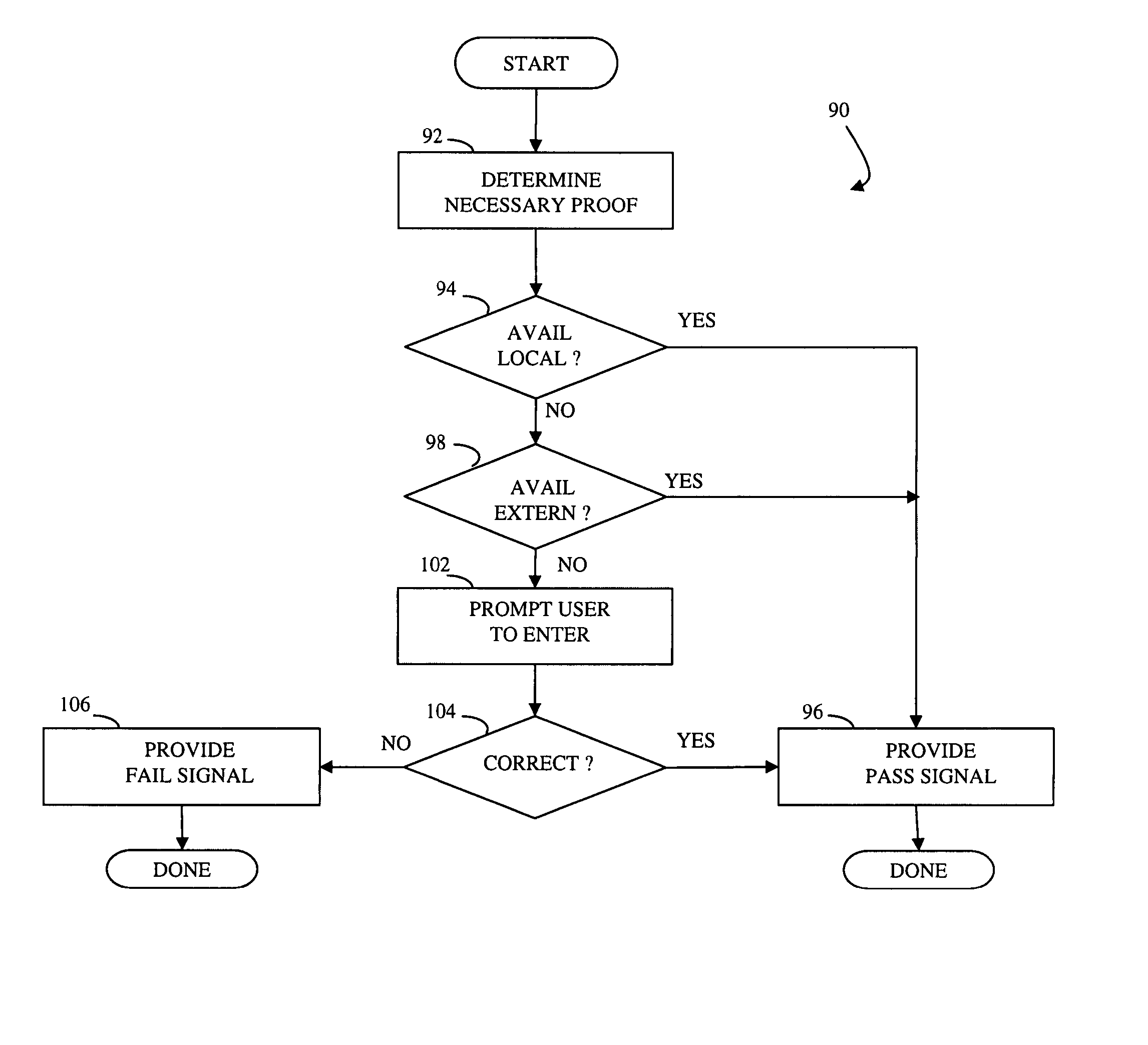
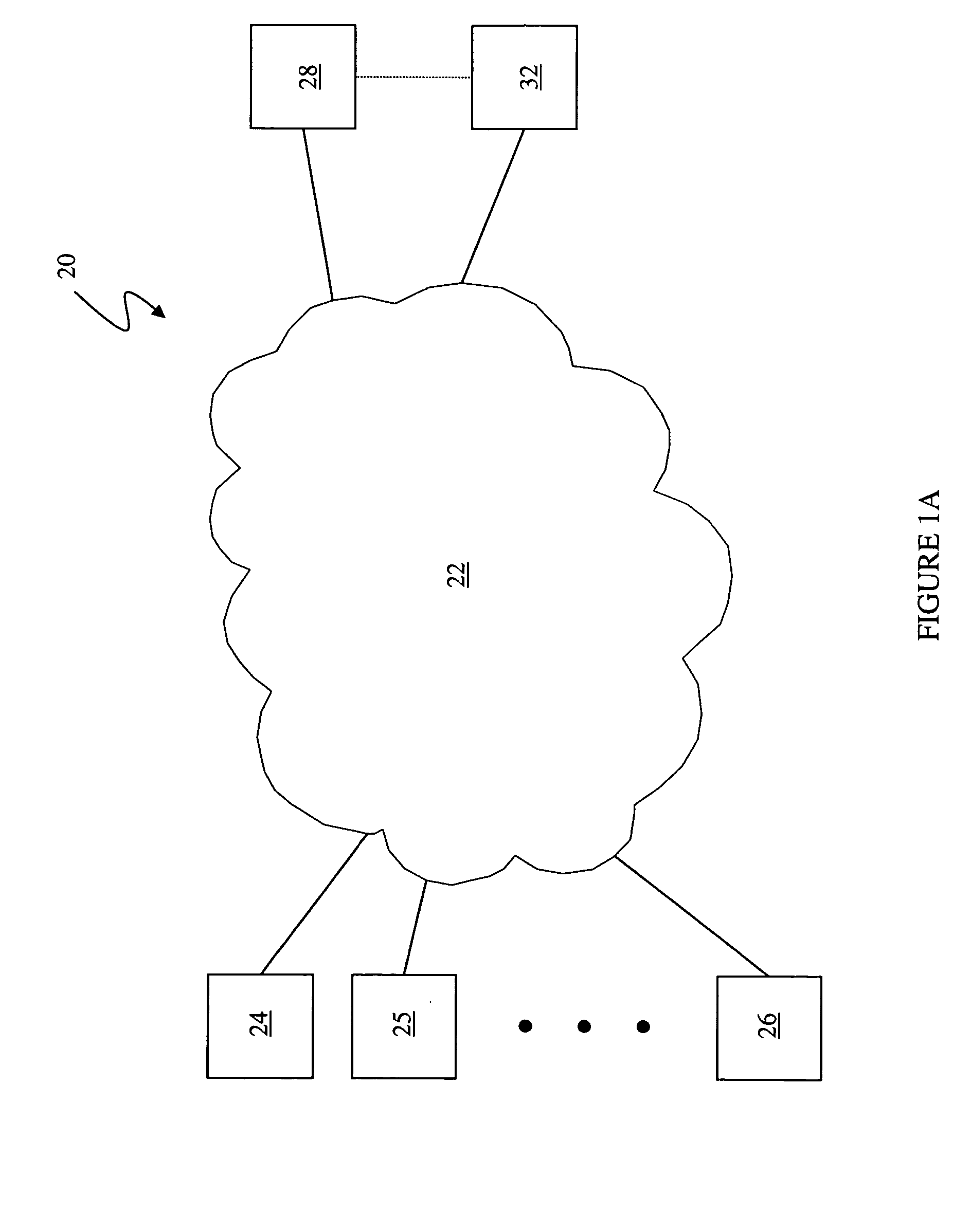
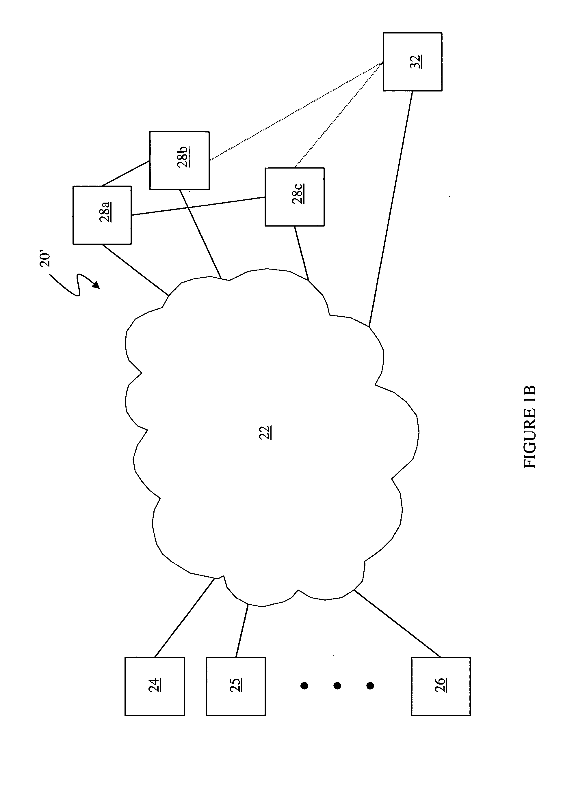
[0021] Referring to FIG. 1A, a diagram 20 illustrates a general connection 22 having a plurality of electronic devices 24-26 coupled thereto. Although the diagram 20 shows three electronic devices 24-26, the system described herein may work with any number of electronic devices. The connection 22 may be implemented by a direct electronic data connection, a connection through telephone lines, a LAN, a WAN, the Internet, a virtual private network, or any other mechanism for providing data communication. The electronic devices 24-26 may represent one or more laptop computers, desktop computers (in an office or at an employees home or other location), PDA's, cellular telephones, disk drives, mass storage devices, or any other electronic devices in which it may be useful to restrict access thereto. In an embodiment herein, the electronic devices 24-26 represent desktop or laptop computers that are used by employees of an organization that wishes to restrict access thereto in case a user / ...
PUM
Abstract
At least one administration entity controls access to an electronic device by the at least one administration entity generating credentials and a plurality of corresponding proofs for the electronic device, wherein no valid proofs are determinable given only the credentials and values for expired proofs, the electronic device receiving the credentials, if access is authorized at a particular time, the electronic device receiving a proof corresponding to the particular time, and the electronic device confirming the proof using the credentials. The at least one administration entity may generate proofs after generating the credentials. A single administration entity may generate the credentials and generate the proofs. There may be a first administration entity that generates the credentials and other administration entities that generate proofs. The first administration entity may also generate proofs or may not. The credentials may be a digital certificate that includes a final value that is a result of applying a one way function to a first one of the proofs. Each of the proofs may be a result of applying a one way function to a future one of the proofs. The digital certificate may include an identifier for the electronic device.
Description
CROSS-REFERENCE TO RELATED APPLICATIONS [0001] This application claims priority to U.S. provisional patent application No. 60 / 482,179 filed on Jun. 24, 2003, which is incorporated by reference herein, and is a continuation-in-part of U.S. patent application Ser. No. 09 / 915,180 filed on Jul. 25, 2001 (pending), which is a continuation of is a continuation of U.S. patent application Ser. No. 09 / 483,125 filed Jan. 14, 2000 (now U.S. Pat. No. 6,292,893), which is a continuation of U.S. patent application Ser. No. 09 / 356,745 filed Jul. 19, 1999 (abandoned), which is a continuation of U.S. patent application Ser. No. 08 / 823,354 filed Mar. 24, 1997 (now U.S. Pat. No. 5,960,083), which is a continuation of U.S. patent application Ser. No. 08 / 559,533 filed Nov. 16, 1995 (now U.S. Pat. No. 5,666,416) which claims priority to U.S. provisional patent application Ser. No. 60 / 006,038 filed on Oct. 24, 1995.BACKGROUND OF THE INVENTION [0002] 1. Technical Field [0003] This application relates to th...
Claims
Application Information
Patent Timeline
Application Date:The date an application was filed.
Publication Date:The date a patent or application was officially published.
First Publication Date:The earliest publication date of a patent with the same application number.
Issue Date:Publication date of the patent grant document.
PCT Entry Date:The Entry date of PCT National Phase.
Estimated Expiry Date:The statutory expiry date of a patent right according to the Patent Law, and it is the longest term of protection that the patent right can achieve without the termination of the patent right due to other reasons(Term extension factor has been taken into account ).
Invalid Date:Actual expiry date is based on effective date or publication date of legal transaction data of invalid patent.
Patent Type & Authority Applications(United States)