Ultrasonic flow meter

a flow meter and ultrasonic technology, applied in the direction of volume/mass flow measurement, measurement devices, instruments, etc., can solve the problem of being unable to accurately measure the flow rate of flowing liquid with the transducer, and achieve the effect of accurately measuring the flow rate of flowing liquid, and reducing the noise of oscillation

Active Publication Date: 2005-01-20
SURPASS IND
View PDF0 Cites 5 Cited by
  • Summary
  • Abstract
  • Description
  • Claims
  • Application Information

AI Technical Summary

Benefits of technology

[0011] According to the present invention as described above, by providing the pair of fixing portions which respectively support the conduit for measurement at the outside side and the internal side of the longitudinal direction of the measurement sections, it is possible to prevent the mixture of the noise of oscilations of the conduit for measurement due to the influence of external forces from externally into the oscilations which are generated from the measurement sections for measuring the flow rate of the flowing liquid. As a result, it is possible to prevent these oscilations from becoming mutually superimposed, and therefore, it becomes possible to perform measurement of the flow rate of the flowing liquid accurately and reliably with this ultrasonic flow meter by reducing the noise of oscilations of the conduit for measurement. In particular, even if the conduit for measurement is made from a resin material, in other words even if the conduit for measurement is not extremely rigid, it is possible to avoid such mutual overlapping of these oscilations.
[0013] According to the present invention as described above, by providing the cutaway portion upon the outer peripheral surface of the conduit for measurement, it becomes possible to reduce the noise of oscilations which are transmitted from externally to the conduit for measurement. In particular, since it is possible easily to provide such a cutaway portion upon the exterior peripheral surface of the conduit for measurement even if the conduit for measurement is relatively thick. Accordingly, in this case, it becomes easy to reduce the noise of oscilations which are transmitted to the conduit for measurement from the outside, and therefore, it becomes possible to perform measurement of the flow rate of the flowing liquid accurately and reliably with this ultrasonic flow meter.

Problems solved by technology

With such a prior art type of ultrasonic flow meter, when the conduit for measurement in to which both ends of the measurement section are fixed is oscilated due to reception of some unintentional external force such as noise or the like, then, when the oscilations are emitted from the transducer for measuring the flow rate of the flowing liquid, these oscilations become mixed with the oscilations of the conduit for measurement which the measurement device has received from externally, and therefore, the problem arises that it may become impossible to measure the flow rate of the flowing liquid accurately with the transducers, due to the ultrasonic signal which is being inputted from the transducer as a measurement oscilation becoming superimposed with these oscilations from externally.
This fact becomes a particularly severe problem when the conduit for measurement is made from a synthetic resin material, since such a conduit for measurement is not a rigid body.

Method used


Image

  • Ultrasonic flow meter
  • Ultrasonic flow meter
  • Ultrasonic flow meter

Examples


Embodiment Construction

[0022] In the following, a preferred embodiment of the ultrasonic flow meter of the present invention will be explained with reference to the drawings.

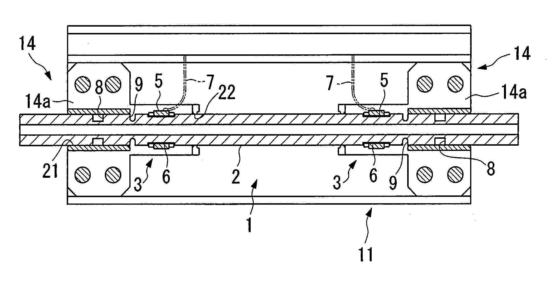
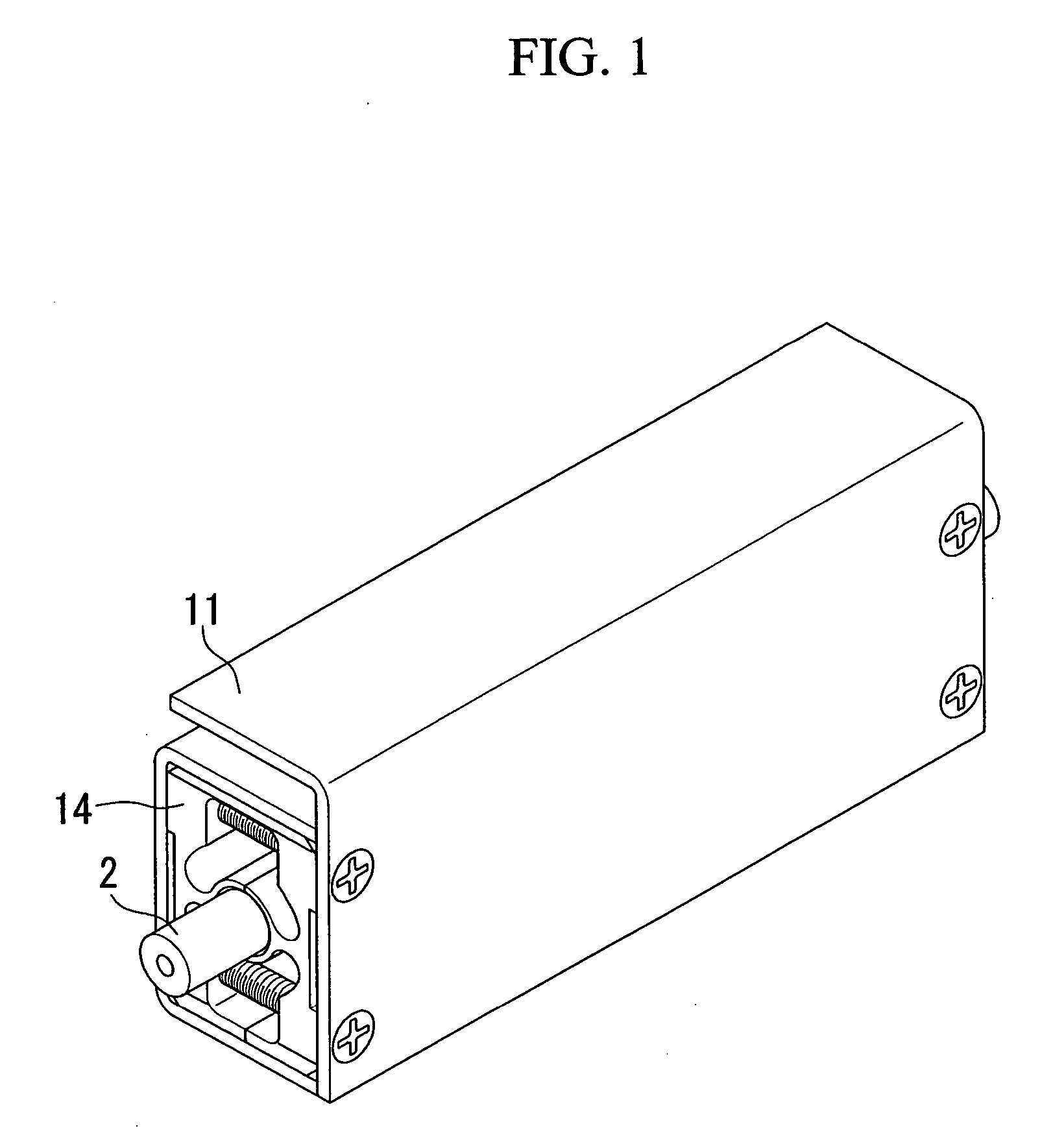
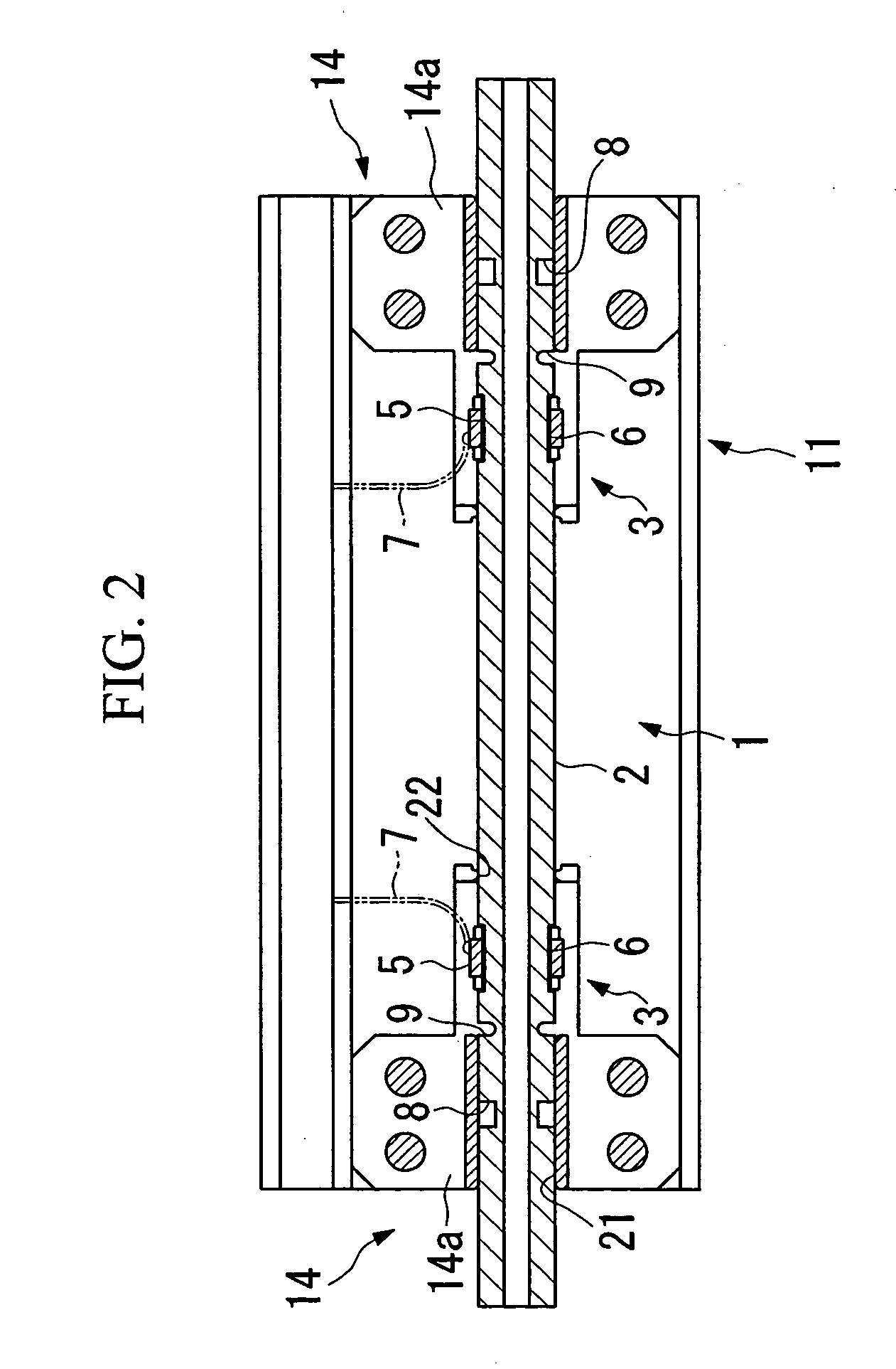
[0023] In FIGS. 1 and 2, the reference symbol 1 denotes an ultrasonic flow meter as a whole. This ultrasonic flow meter 1 is composed of a conduit for measurement 2 in which a liquid flows therein and made from a synthetic resin which has excellent chemical resistance such as a polyvinyl chloride or fluororesin or the like, and a pair of measurement sections 3 which are provided in this conduit for measurement and are spaced apart along a longitudinal direction of the conduit for measurement by a certain interval, for example.

[0024] Each of the measurement sections 3 is made by closely fitting a transducer 5 upon the outer circumferential surface of the conduit for measurement 2. Furthermore, the reference symbols 7 in the figure denote lead wires for these transducers 5. In addition, cutaway portions 8 and 9 are provided upon the o...


PUM


Abstract

The present invention proposes an ultrasonic flow meter, comprising a conduit for measurement in which a liquid flows therein, and a pair of measurement sections which are provided in said conduit for measurement and are spaced apart by a certain interval along its longitudinal direction, and which obtains the flow velocity of said flowing liquid from the difference in the propagation time periods of ultrasonic in the two opposite directions between these measurement sections, and thereby measures the flow rate thereof; wherein a pair of fixing portions are provided which respectively support said conduit for measurement at the exterior side and also at the interior side in the longitudinal direction of said measurement sections.

Description

BACKGROUND OF THE INVENTION [0001] 1. Field of the Invention [0002] The present invention relates to an ultrasonic flow meter which measures the flow rate of a liquid which is flowing in a conduit or the like by using ultrasonic waves. [0003] Priority is claimed on Japanese Patent Application No. 2003-176421, filed Jun. 20, 2003, the content of which is incorporated herein by reference. [0004] 2. Description of the Related Art [0005] As a flow meter which measures the flow rate of a liquid which is flowing through a conduit, there is a per se known type of ultrasonic flow meter which utilizes ultrasonics. [0006] In this ultrasonic flow meter, there is provided, in a conduit for measurement of the flow of the flowing liquid, a measurement section which comprises transducers spaced apart by an interval in the longitudinal direction. An ultrasonic pulse which is generated from a first one of these transducers is received by another of these transducers, and further an ultrasonic pulse ...

Claims


Application Information

Patent Timeline
Patent Type & Authority Applications(United States)
IPC IPC(8): G01F1/66
CPCG01F1/667G01F1/662
Inventor IMAI, HIROSHITAKADA, AKIRAHASUNUMA, MASAHIRO
Owner SURPASS IND
Why Eureka
Try Eureka