

Coriolis mass flowmeter and method for operating a Coriolis mass flowmeter
- Summary
- Abstract
- Description
- Claims
- Application Information
AI Technical Summary
Benefits of technology
Problems solved by technology
Method used
Image

Examples
Embodiment Construction
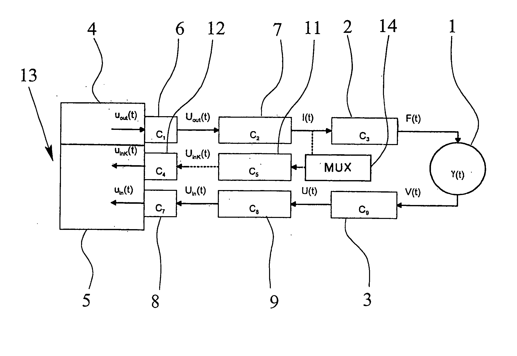
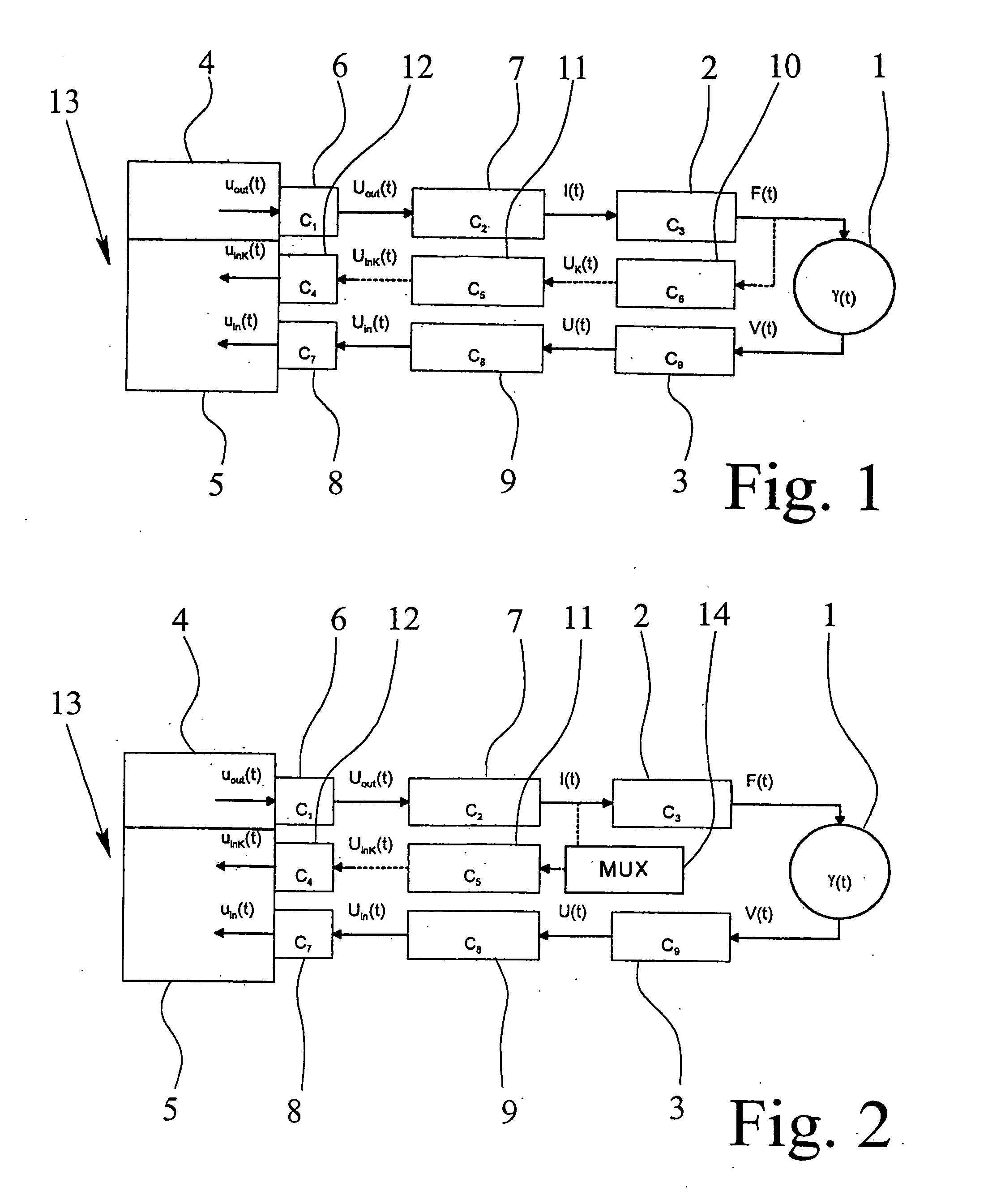
FIG. 1 is a schematic illustration of a Coriolis mass flowmeter according to a first preferred embodiment of the invention. The Coriolis mass flowmeter according to this first preferred embodiment incorporates a measuring tube 1 that is energized and caused to oscillate by way of a dual-channel excitation signal path terminating in two oscillators 2. The resulting oscillations of the measuring tube 1 through which travels a flowing medium are registered by two oscillation detectors 3.
An activator 4 serves to activate the oscillators 2 via the excitation signal path while an evaluation unit 5 is provided for analyzing the oscillations of the measuring tube 1 sensed by the oscillation detectors 3, with the activator 4 and the evaluation unit 5 being physically unitized into an activating and evaluation system 13. The dual-channel excitation signal path includes multiple excitation signal path devices, these being digital / analog converters 6, power sources 7 and the aforementioned osc...
PUM
 Abstract
Description
Claims
Application Information