Cutter with laser generator that irradiates cutting position on workpiece to facilitate alignment of blade with cutting position
a laser generator and cutter technology, applied in the field of cutters, can solve the problems of only being able to irradiate the workpiece, undesirable overall enlargement of the cutter, etc., and achieve the effect of eliminating looseness and easy adjustmen
- Summary
- Abstract
- Description
- Claims
- Application Information
AI Technical Summary
Benefits of technology
Problems solved by technology
Method used
Image
Examples
first embodiment
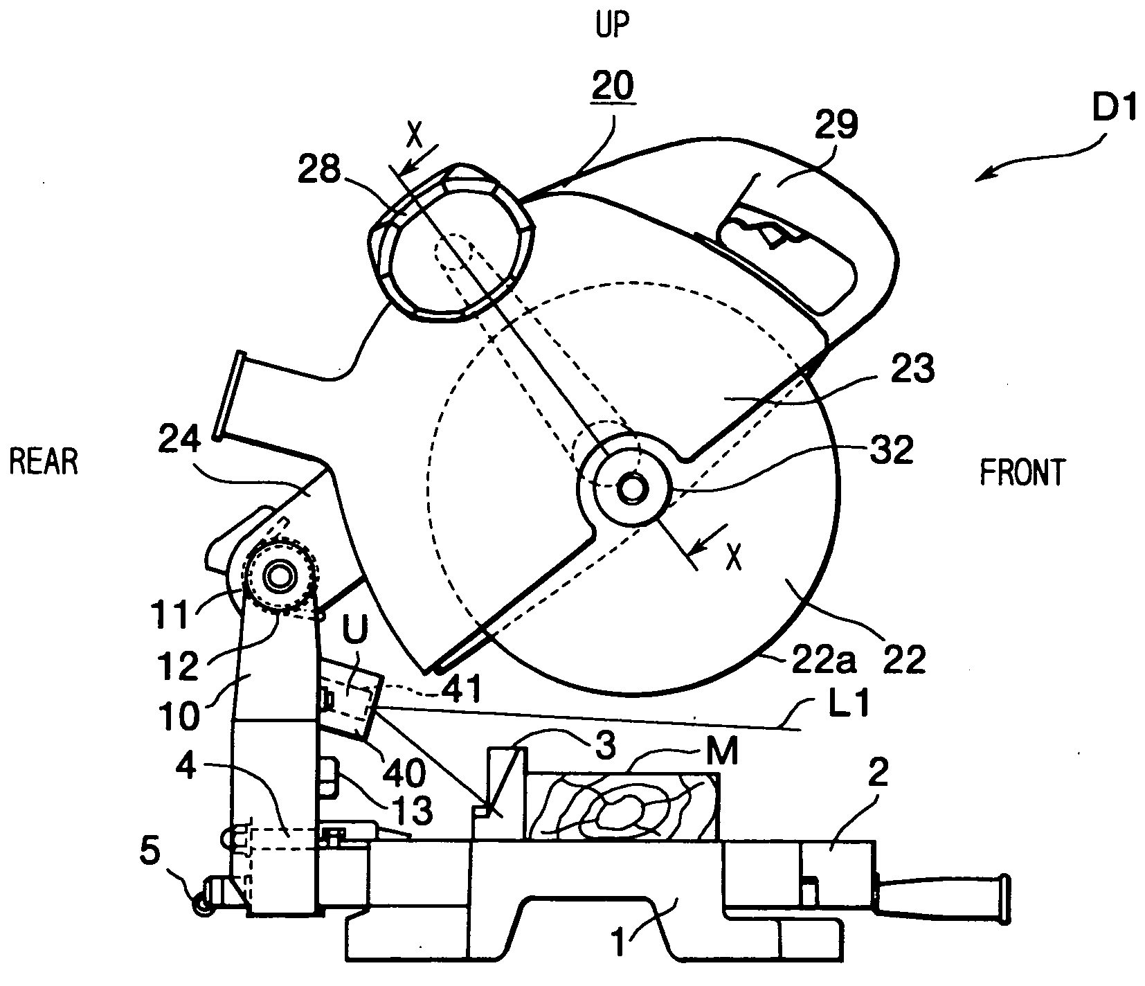
[0081] First, a cutter D1 will be described while referring to FIGS. 8 to 14. As shown in FIG. 8, the cutter D1 has a base 1, a turntable 2, a fence 3, a holder shaft 4, a holder 10, a clamp lever 5, a shaft 11, a cutter mechanism 20, and a laser unit U. The turntable 2 is supported on the center of the base 1 so as to be freely rotatable horizontally. The upper surface of the turntable 2 shares the same plane with the upper surface of the base 1. A workpiece M, such as a wooden board, is placed on the upper surfaces of the base 1 and the turntable 2. The fence 3 is fixed on the upper surface of the base 1 to support the side surface of the workpiece M. The holder 10 is supported in an upright posture on the rear end of the turntable 2 by the holder shaft 4. The axial center of the holder shaft 4 is aligned substantially with the upper surface of the turntable 2. The holder 10 can be pivoted leftward or rightward with respect to the surface of the turntable 2 about the holder shaft...
eighth embodiment
[0122] As shown in FIGS. 33 to 35, an angular indentation 40h is formed in the inner surface of the left wall of the support member 840, near the front of the support member 840. An angular protrusion 41f is formed at the left side of the laser generator 841, at a position corresponding to the position of the angular indentation 40h. Other configuration is the same as described for the
[0123] With the configurations of the eighth and ninth embodiments, the position where the laser light L1 falls incident on the workpiece M can be adjusted in precise alignment with vertical and horizontal reference lines X, Y in a manner similar to that described in the seventh embodiment, so that the laser light L1 can be properly and easily positioned into alignment with a desired cutting position.
[0124] Next, the tenth embodiment of the present invention will be described while referring FIGS. 36 to 39. The cutter according to the tenth embodiment has substantially the same configuration as the cu...
PUM
| Property | Measurement | Unit |
|---|---|---|
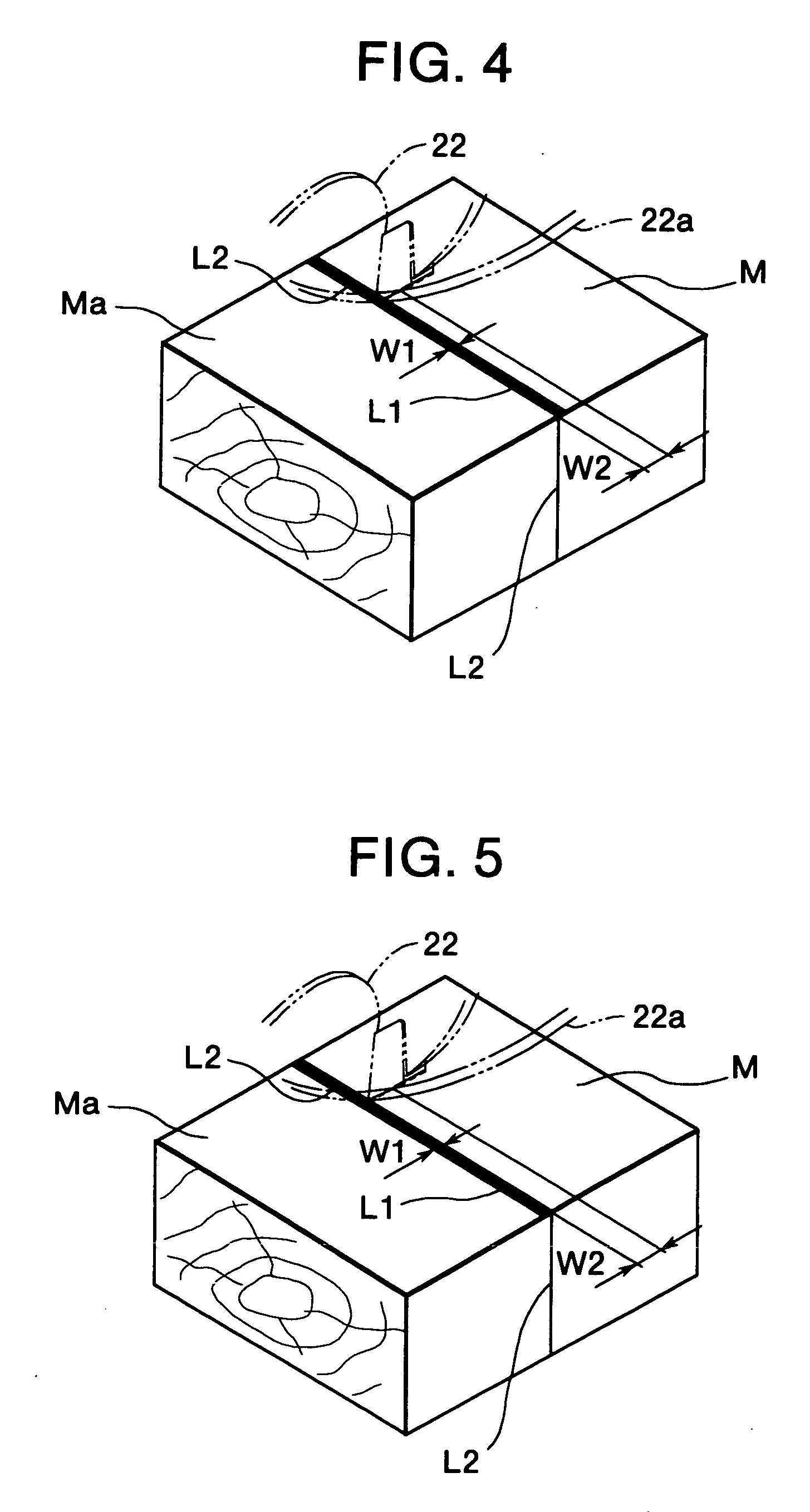
| width W2 | aaaaa | aaaaa |
| outer diameter | aaaaa | aaaaa |
| width W1 | aaaaa | aaaaa |
Abstract
Description
Claims
Application Information
 - R&D
- Intellectual Property
- Life Sciences
- Materials
- Tech Scout
- Unparalleled Data Quality
- Higher Quality Content
- 60% Fewer Hallucinations
Browse by: Latest US Patents, China's latest patents, Technical Efficacy Thesaurus, Application Domain, Technology Topic, Popular Technical Reports.
© 2025 PatSnap. All rights reserved.Legal|Privacy policy|Modern Slavery Act Transparency Statement|Sitemap|About US| Contact US: help@patsnap.com


