Heat exchanger and tube for heat exchanger

a technology of heat exchanger and tube, which is applied in the direction of tubular elements, lighting and heating apparatus, and stationary conduit assemblies, etc. it can solve the problems of unsatisfactory core width with respect to mounting space of heat exchanger, and the width of tubes to be inserted into the tanks must be extremely small with respect to the outer diameter of the tanks, so as to achieve efficient assembly and small tank volume

Inactive Publication Date: 2005-01-20
ZEXEL VALEO CLIMATE CONTROL CORP SAITAMA
View PDF7 Cites 40 Cited by
  • Summary
  • Abstract
  • Description
  • Claims
  • Application Information

AI Technical Summary

Benefits of technology

[0046] Specifically, the ends of the tubes before bending are inserted into the slots and bent to a prescribed angle. By configuring as above, the tubes and the tanks can be assembled efficiently.
[0047] The invention described in Claim 21 of the present application is the heat exchanger according to any of Claims 3 to 20, wherein the heat exchanger is used for a refrigeration cycle which circulates the refrigerant, and the refrigeration cycle has a pressure on a high-pressure sid

Problems solved by technology

Here, when the tanks are made thick, there is a disadvantage that the width of the tubes to be inserted into the tanks must be made extremely small with respect to the outer diameter of the tanks.
In other words, the tank having a large thickness has a large difference between the outer diameter and the in

Method used


Image

  • Heat exchanger and tube for heat exchanger
  • Heat exchanger and tube for heat exchanger
  • Heat exchanger and tube for heat exchanger

Examples


second embodiment

[0093] Then, the invention will be described with reference to FIG. 7. As shown in FIG. 7, the radiator 300 of this embodiment is configured by overlaying a first core 300a and a second core 300b in an airflow direction. The tank 310 is disposed on both ends of the first core 300a and the second core 300b. And, on one side of the first core 300a and of the second core 300b, the inlet 320 for the refrigerant is disposed on the tank 310 into which the ends 301a of the tubes 301 of the first core 300a are inserted, and the outlet 330 for the refrigerant is disposed on the tank 310 into which the ends 301a of the tubes 301 of the second core 300b are inserted. On the other side of the first core 300a and of the second core 300b, the tank 310 into which the ends 301a of the tubes 301 of the first core 300a are inserted and the tank 310 into which the ends 301a of the tubes 301 of the second core 300b are inserted are communicated. The refrigerant successively passes through the first cor...

third embodiment

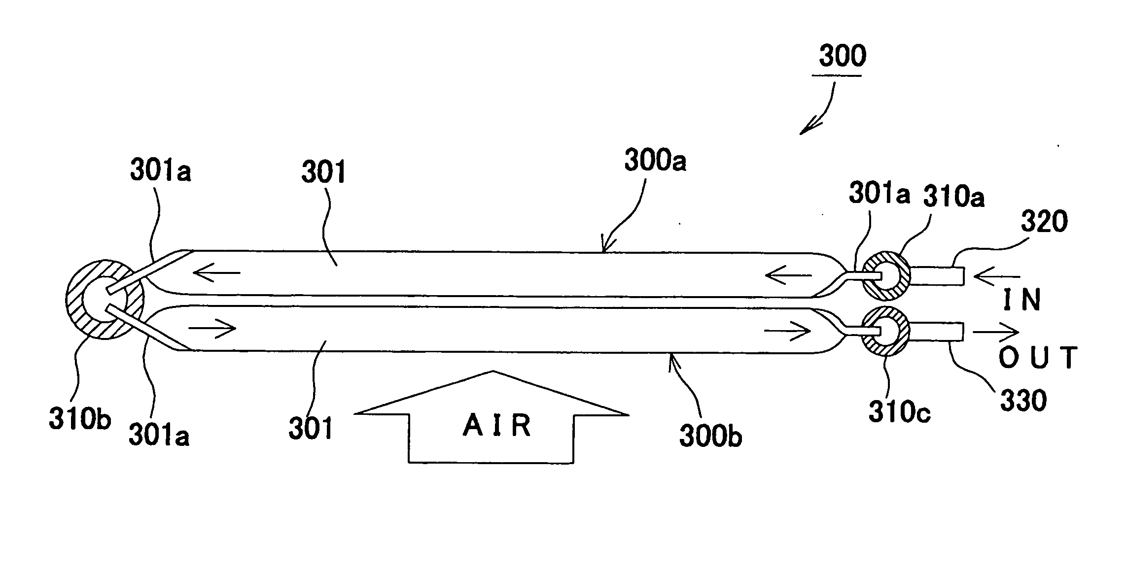
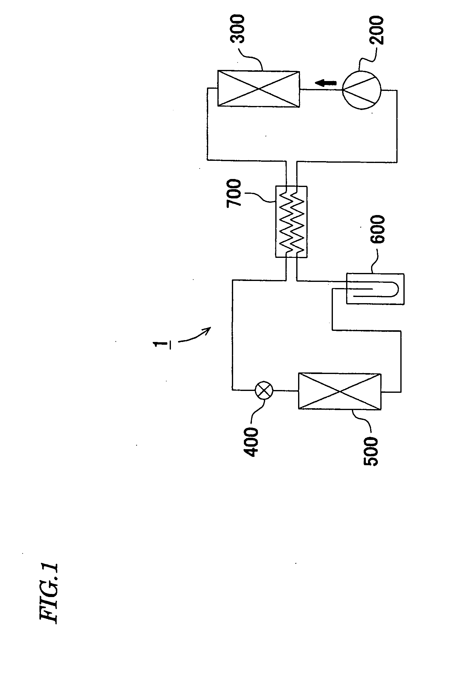
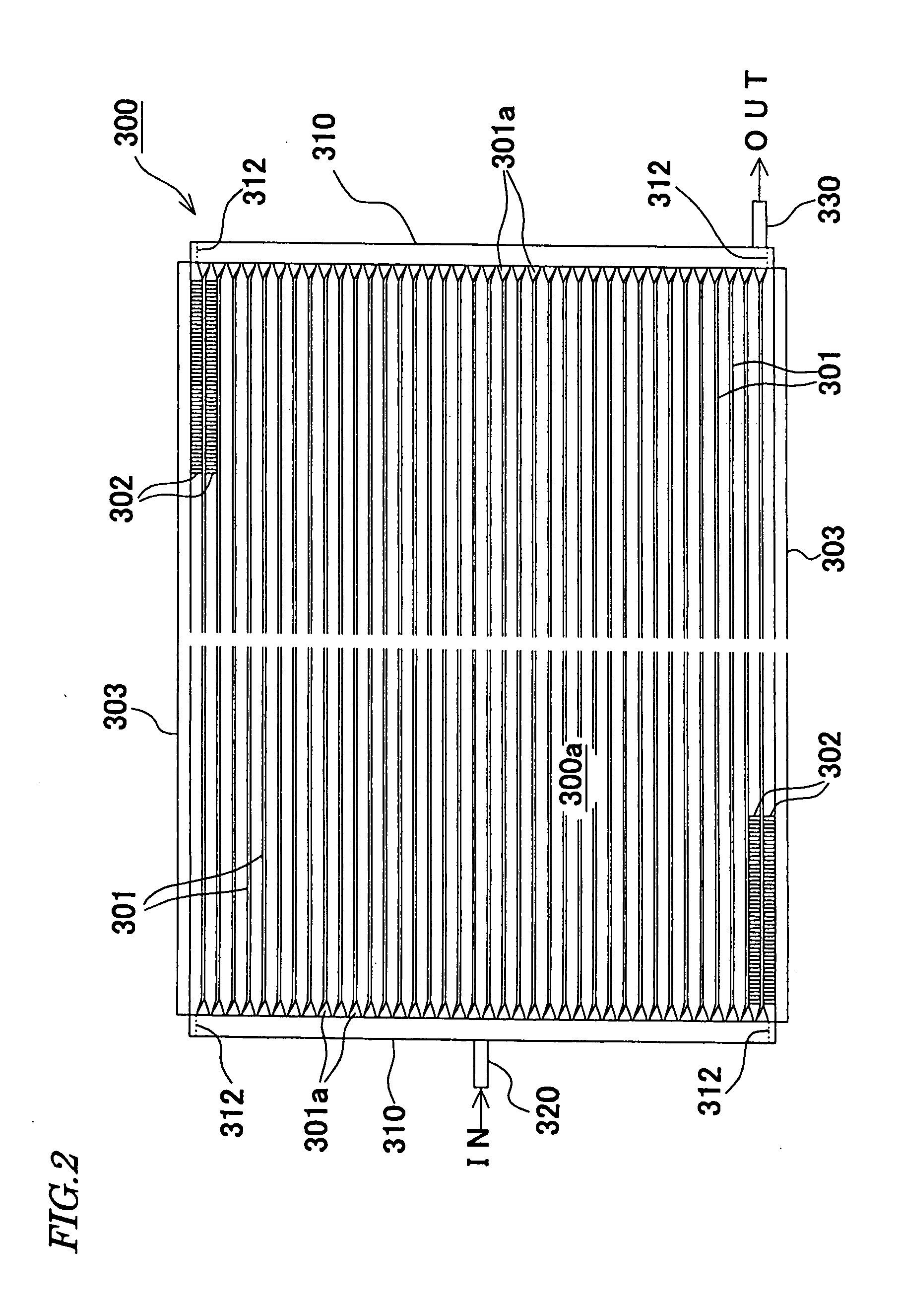
[0095] Next, the invention will be described. As shown in FIG. 8 to FIG. 10, the radiator 300 as the heat exchanger of this embodiment is provided with the first core 300a and the second core 300b which are comprised of lamination of the flat tubes 301 for flowing the refrigerant and the corrugated fins 302, a first tank 310a, a second tank 310b and a third tank 310c each having a pipe shape into which the ends 301a of the tubes 301 are inserted, the inlet 320 which is disposed on the first tank 310a and has a pipe shape for the refrigerant and the outlet 330 which is disposed on the third tank 310c and has a pipe shape for the refrigerant. The refrigerant sent from the compressor 200 enters the inlet 320, and the refrigerant discharged from the outlet 330 is sent to the expansion valve 400. In FIG. 8 to FIG. 10, arrows indicate the flowing directions of the refrigerant in the radiator 300, and the outline arrows indicate the airflow direction to the first core 300a and the second c...

fourth embodiment

[0104] Next, the invention will be described with reference to FIG. 17 and FIG. 18. As shown in FIG. 17, the radiator 300 of this embodiment is disposed on the windward of a radiator 800 of a vehicle, the positions of the first tank 310a and the third tank 310c are displaced in a direction orthogonal to the airflow direction on one side of the first core 300a and of the second core 300b, and the inlet 320 and the outlet 330 are directed toward the downwind side of the airflow direction. The tubes 301 of the first core 300a are determined to be somewhat shorter than the tubes 301 of the second core 300b. The other structure is the same as the previous embodiment.

[0105] According to this embodiment, the radiator 300 can be configured more rationally, and the piping structure in the layout of the refrigeration cycle 1 of a vehicle can be simplified. Especially, the inlet 320 and the outlet 330 in the pipe form for flowing a high-pressure refrigerant and piping to be connected to the in...


PUM


Abstract

A heat exchanger and its tubes, wherein the heat exchanger includes a core 300a, having a lamination of flat tubes 301 for flowing a refrigerant and corrugated fins 302, and tanks 310 having slots for insertion of the ends of tubes, the core is configured to have the flat surfaces of the tubes in parallel with the airflow direction, and the tubes have their ends 301a twisted in the width direction by 90° with respect to the airflow direction. A heat exchanger for a supercritical refrigeration cycle has tanks 310a, 310c displaced in a direction orthogonal to the airflow direction on one side of plural cores 300a, 300b which are overlaid in the airflow direction, and an inlet 320 and an outlet 330 for the refrigerant are oriented toward the windward side or the downwind side of the airflow direction.

Description

TECHNICAL FIELD [0001] The present invention relates to a heat exchanger, which is provided with a core comprising flat tubes for flowing a refrigerant and corrugated fins, and tanks with slots for insertion of the ends of the tubes, and carries out heat exchange by flowing air to the core and transferring heat to the core. BACKGROUND ART [0002] A heat exchanger such as a radiator or an evaporator to be used for a refrigeration cycle is known that a core is comprised of plural flat tubes and plural corrugated fins, stacked alternately and the ends of the tubes are inserted into pipe-shape tanks. The flat surfaces of the tubes are configured to be parallel with an airflow direction. The refrigerant is introduced inside from the tank, flowed through the tubes while carrying out heat exchange with heat transferred to the core and discharged outside from the tank. [0003] As the refrigerant for the refrigeration cycle, a fluorocarbon refrigerant including a substitute fluorocarbon has be...

Claims


Application Information

Patent Timeline
IPC IPC(8): F28D1/04F28D1/053F28F1/02F28F9/18F28F9/26
CPCF28D1/0417F28D1/0435F28D1/05391F28F9/262F28F1/025F28F9/182F28F1/022
Inventor TAKANO, AKIHIKO
Owner ZEXEL VALEO CLIMATE CONTROL CORP SAITAMA
Why Eureka
Try Eureka