Memory card with and without enclosure

Active Publication Date: 2005-01-20
SANDISK TECH LLC
View PDF82 Cites 58 Cited by
  • Summary
  • Abstract
  • Description
  • Claims
  • Application Information

AI Technical Summary

Benefits of technology

[0014] The present invention, roughly described, pertains to a small memory card tha

Problems solved by technology

First, the test pins that are cut off use real estate on the circuit board.
Second, if the memory card fails in the field, there are no test pins to test the device in order to determine why the memory card failed.
There will be a small air gap between the bottom lid and the bottom of the circuit board While this design works well, the top and bottom lids are relatively expensive to manufacture.
Additionally, t

Method used


Image

  • Memory card with and without enclosure
  • Memory card with and without enclosure
  • Memory card with and without enclosure

Examples


Embodiment Construction

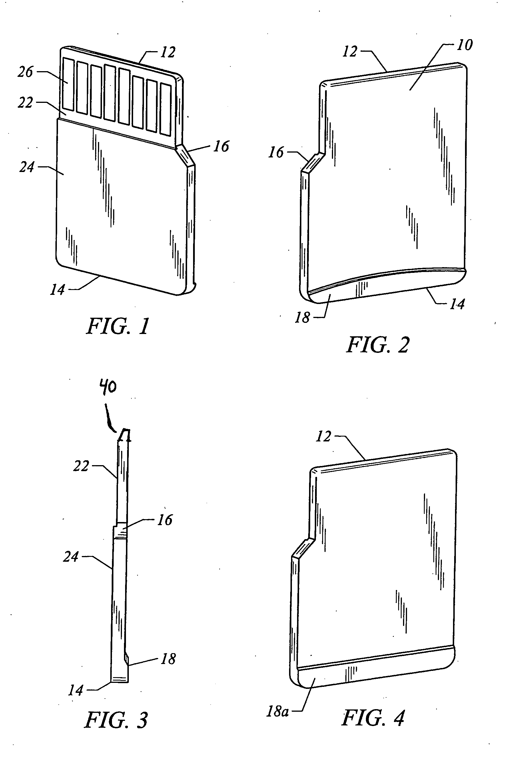
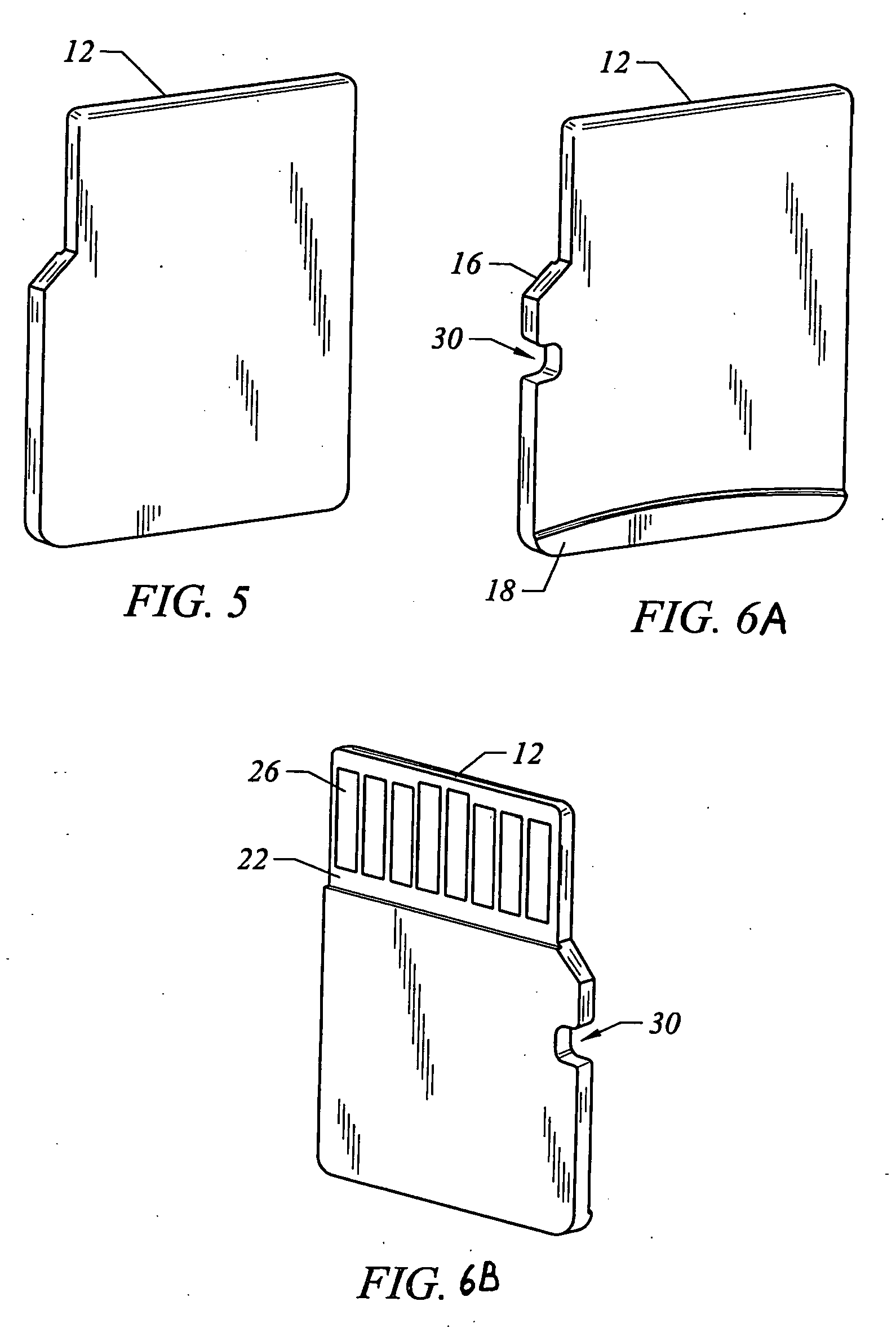
[0055]FIGS. 1-10 depict various embodiments of a memory card. For example, FIG. 1 is a perspective view of the bottom of a memory card according to a first embodiment of the present invention. FIG. 2 is a perspective view of the top of the memory card according to the first embodiment of the present invention. FIG. 3 is a side view of the memory card according to the first embodiment of the present invention. The memory card of FIGS. 1-3 includes a top surface 10, a bottom surface, a front surface 12, a back surface 14 and two side surfaces. One of the side surfaces has an angle portion 16. Top surface 10 has a raised portion 18 adjacent to back surface 14. Raised portion 18 allows the memory card to be more easily grabbed by a human hand (or mechanical device) and also provides additional room to store passive devices such as capacitors and / or resistors. Note that raised portion 18 of FIG. 1 has a curved profile. The bottom surface includes a first portion 22 and a second portion 2...


PUM

PropertyMeasurementUnit
Moldableaaaaaaaaaa

Abstract

The present invention, roughly described, pertains to a small memory card that includes features which allow the memory card to be more easily handled by a user. In various embodiments, the memory card can include a chamfer and/or a raised portion that allows the memory card to be more easily grabbed by a human hand (or mechanical device) and also provides additional room to store passive devices such as capacitors and/or resistors. Because different electronic devices use different types of memory cards, an adaptor is provided that allows the memory cards disclosed herein to be used in ports or connectors on electronic devices that are meant for other types of memory cards.

Description

[0001] This application is a continuation-in-part application of the following three application: (1) U.S. patent application Ser. No. 10 / 621,882, entitled “Peripheral Card with Hidden Test Pins,” filed Jul. 17, 2003 by Hem P. Takiar; (2) U.S. Design application Ser. No. 29 / 186,546 entitled “Memory Card,” filed Jul. 17, 2003 by Hem P. Takiar; and (3) U.S. Design application Ser. No. 29 / 194,064 entitled “Memory Card,” filed Nov. 19, 2003 by Takiar et al. All three of these applications are incorporated herein by reference CROSS-REFERENCE TO RELATED APPLICATIONS [0002] This Application is also related to the following additional United States Patent Applications, both of which are incorporated herein by reference in their entirety: [0003]“Method For Efficiently Producing Removable Peripheral Cards,” application Ser. No. 10 / 602,373, filed Jun. 23, 2003, Hem P. Takiar; and [0004]“Memory Card With Raised Portion,” application Ser. No. 10 / 782,969, filed Feb. 20, 2004, Hem P. Takiar.BACKGR...

Claims


Application Information

Patent Timeline
IPC IPC(8): G06K19/077H05K1/02H05K1/11H05K3/28
CPCG06K13/0825Y10T29/4913G06K19/07732H01L2224/32145H01L2224/48091H01L2224/48227H01L2924/01004H01L2924/1815H01L2924/19041H05K1/02H05K1/0268H05K1/117H05K3/284H05K2201/09045H05K2201/09154H05K2203/0271G06K19/077H01L2924/00014
Inventor TAKIAR, HEM P.MILLER, ROBERT
Owner SANDISK TECH LLC
Why Eureka
Try Eureka