Fuel cap

a fuel cap and cylinder head technology, applied in the field of fuel caps, can solve the problems of difficult to obtain the necessary and satisfactory air tightness of the fuel cap, difficult to achieve quality control, and inability to work, and achieve easy and reliable turning operation, uniform air tightness, and low torque

Inactive Publication Date: 2005-01-20
ASTEER
View PDF19 Cites 9 Cited by
  • Summary
  • Abstract
  • Description
  • Claims
  • Application Information

AI Technical Summary

Benefits of technology

[0035] First, the closure body does not receive the influence of the seal ring during the time from the securing-started stage to the securing-finished stage, so that the fuel cap can be turned with a comparatively low torque. Moreover, since the annular sleeve surface, which the stopper projections run on and are sliding-contacted with, is formed with incline between the stopper recesses, the turning operation of the fuel cap in the inclining direction of the inclined surfaces becomes easy, and the oil filler port can be opened and closed reliably without encountering the interruption during the turning operation of the fuel cap. The stopper projections of the closure body fit into the stopper recesses of the sleeve in the securing-started stage and the securing-finished stage, so that the fuel cap becomes stable and is not turned inadvertently. Thus, the fuel cap according to the present invention is effective in turning operation itself easily and reliably, and, moreover, effective to maintain the shut of the oil filler port stable in the securing-finished stage.
[0036] Second, the air-tightness of the fuel cap is secured by pressure-contacting the seal ring with the inner side surface of the oil filler port in radius direction from the center thereof. Therefore, there is advantage that substantially uniformed air tightness can be obtained in a wide range from the securing-started stage in which the seal ring fits in the oil filler port to the securing-finished stage. The fuel cap according to the present invention can be tightly secured to the oil filler port by only a horizontal turning op

Problems solved by technology

Therefore, it is necessary that the positional relation of the flange and the dimensional accuracy of each part determining this positional relation be set high, and this poses a problem of rendering the quality control difficult.
Secondly, a load transmitted to the seal ring via the flange merely contributes to the occurrence of compression deformation of the seal ring in view of the direct effect of the load, and does not work so as to press the seal ring against a seal surface (end of the oil filler port) for the attainment of the air-tightness of the fuel cap.
It is difficult to o

Method used


Image

  • Fuel cap
  • Fuel cap
  • Fuel cap

Examples


Embodiment Construction

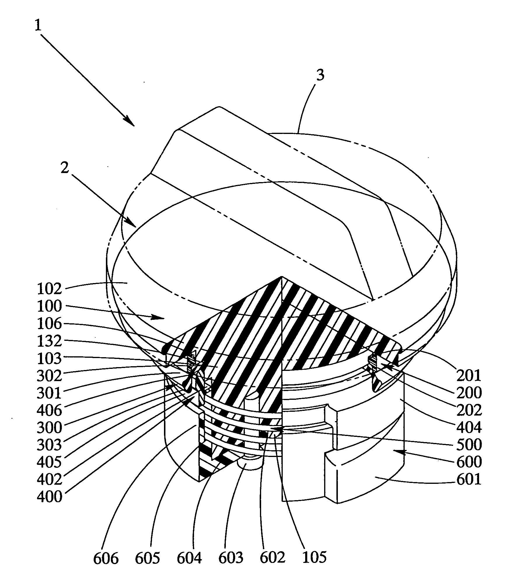
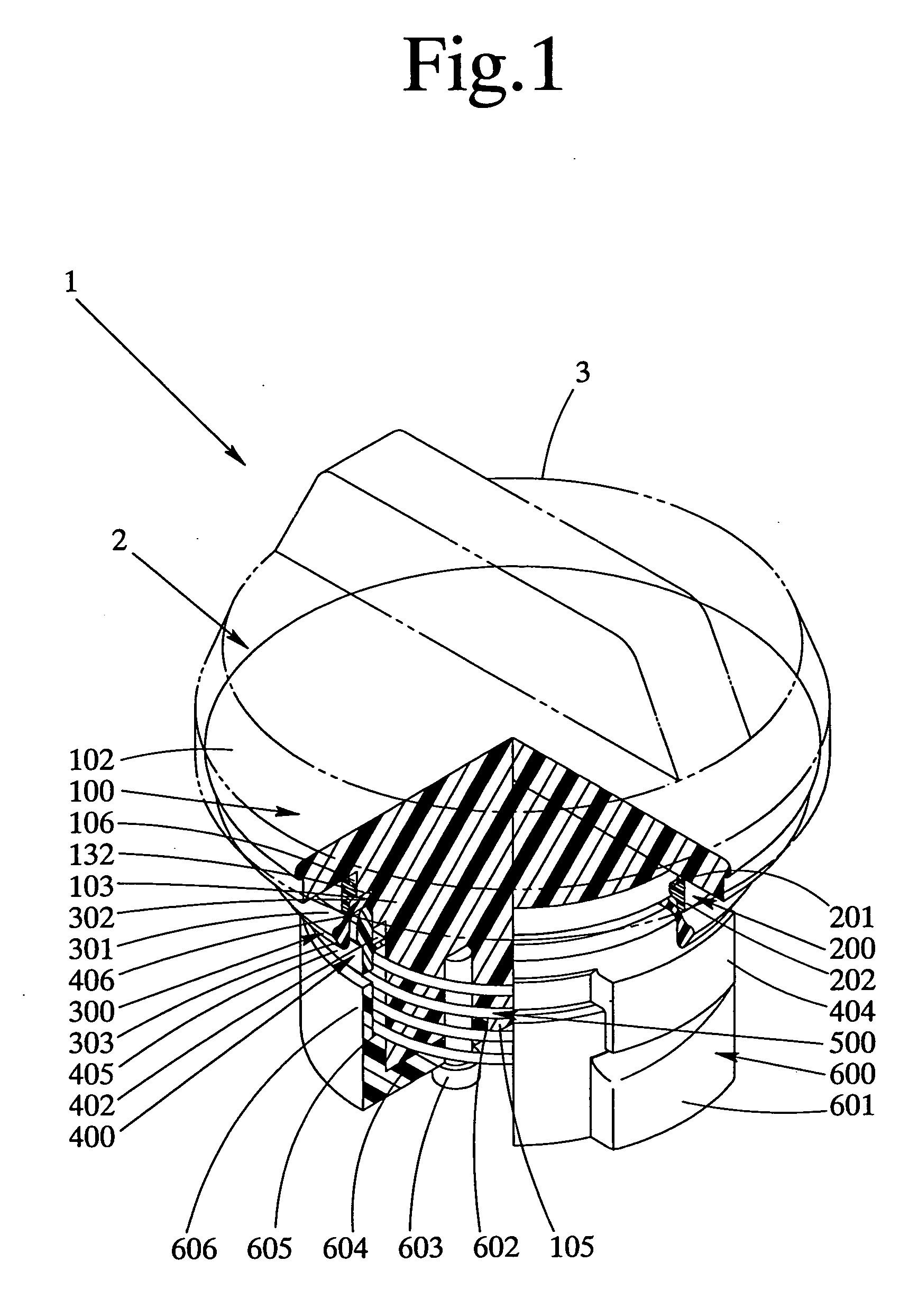
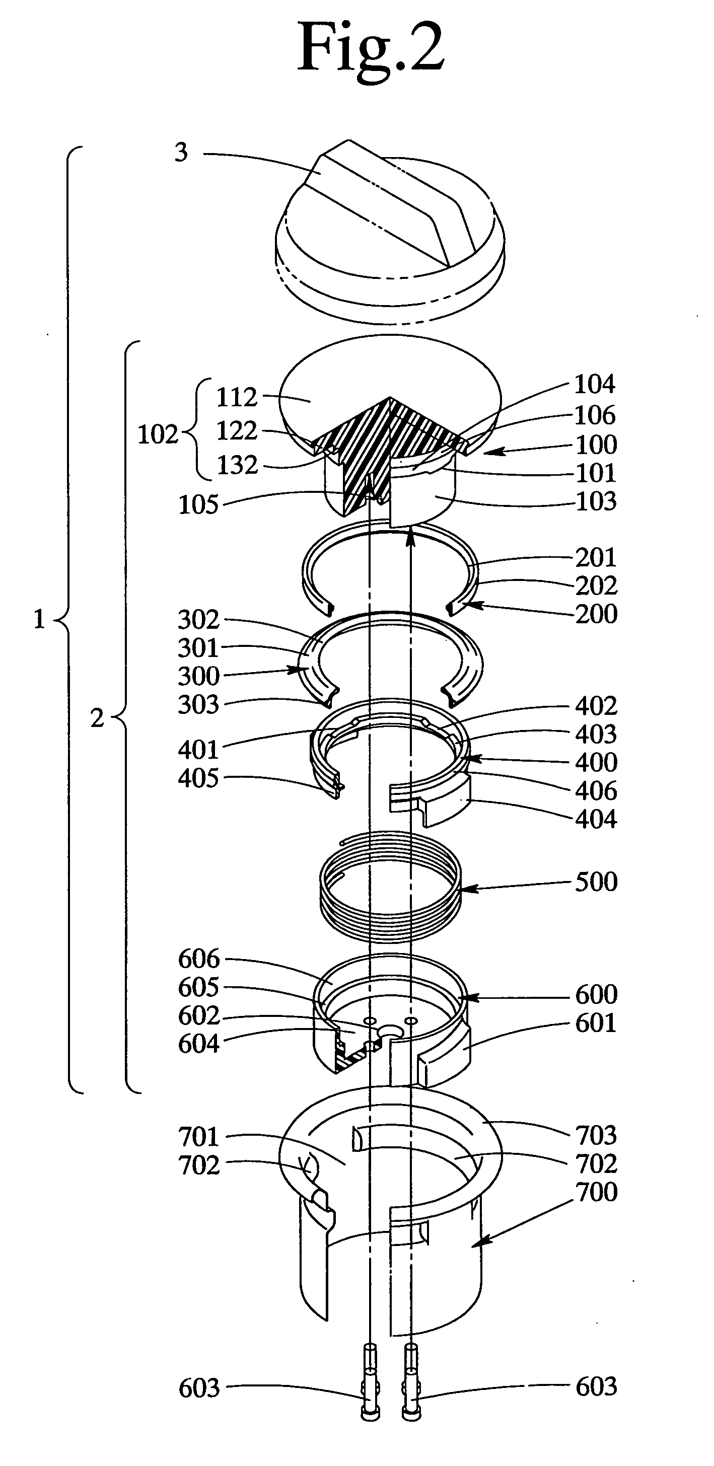
[0065] The modes of embodiments of the present invention will now be described with reference to the drawings.

[0066] The fuel cap 1 is formed as shown in FIGS. 1 and 2, by fixing a fuel cap turning handle 3 to a multi-step head portion 102 including a head top 112 thereof, an upper step 122 thereof and a lower step 132 thereof in a closure body 100 of a closure 2 based on the present invention. The closure 2 based on the present invention is formed into a unitary structure by fitting a retainer ring 200 around the lower step 132 of the head portion 102 of the closure body 100, and a seal ring 300, a sleeve 400 and a coiled spring 500 in the mentioned order in the downward direction around a trunk portion 103 extending from the lower step 132 of the head portion 102 in the axially downward direction, and connecting an engagement member 600 to a lower end of the trunk portion 103. These members except the seal ring 300 are unitary molded products of mainly a synthetic resin, and the ...


PUM


Abstract

The present invention provides a fuel cap having a high operability while maintaining the air-tightness thereof at a necessary and sufficient level. The closure includes a closure body having a head portion, a trunk portion and an annular trunk surface having stopper projections; a seal ring; a sleeve; a coiled spring; and an engagement member having engagement projections. The fuel cap is formed by assembling the seal ring around the annular surface of the trunk portion of the closure body and the sleeve with the trunk portion in the mentioned order, interposing the coiled spring between the sleeve and engagement member, and connecting the engagement member to the trunk portion of the closure body.

Description

BACKGROUND OF THE INVENTION [0001] 1. Field of the Invention [0002] The present invention relates to a fuel cap for a fuel tank for a motor vehicle. [0003] 2. Description of the Related Art [0004] Although a fuel cap for a fuel tank for a motor vehicle is a simple part, it is important to maintain the high air-tightness function of the cap with respect to an oil filler port in a stage in which the fuel cap is turned in the closing direction with respect to an oil filler port and thereby completely finished the securing operation. This stage is hereinafter referred to as a “securing-finished” stage. The improvement of the operability of the fuel cap turning operation from a stage in which the fuel cap is inserted into the fuel filler port and started being turned in the closing direction (, and this stage is hereinafter refereed to as a “securing-started” stage,) to the securing-finished stage, i.e. the simplification of the fuel cap opening and closing operations and, especially, th...

Claims


Application Information

Patent Timeline
IPC IPC(8): B60K15/04B60K15/05
CPCB60K15/0406Y10S220/33B60K2015/0451
Inventor YOSHIDA, HIROMITSUONO, TAKAMI
Owner ASTEER
Why Eureka
Try Eureka