Mixed mode mounting assembly for shock/strut rod

Inactive Publication Date: 2005-01-20
BASF CORP
View PDF24 Cites 27 Cited by
  • Summary
  • Abstract
  • Description
  • Claims
  • Application Information

AI Technical Summary

Benefits of technology

[0012] Accordingly, the subject invention incorporates the simplified and relatively inexpensive configuration of the single path design as well as the operational advantages of the dual path design. In particular, the subject invention incorporates the advantage of the dual path design by having the intermittent high amplitude loads tr

Problems solved by technology

However, due to the configuration and positioning of the insulators in the single path design, the large loads due to intermittent high amplitude movements of the wheel suspension system are also transmitted through the insulators.
As a result, the small amplitude vibration or displacement isolation characteristics are diminished.
However, unlike the single path design, the intermittent high amplit

Method used


Image

  • Mixed mode mounting assembly for shock/strut rod
  • Mixed mode mounting assembly for shock/strut rod
  • Mixed mode mounting assembly for shock/strut rod

Examples


Embodiment Construction

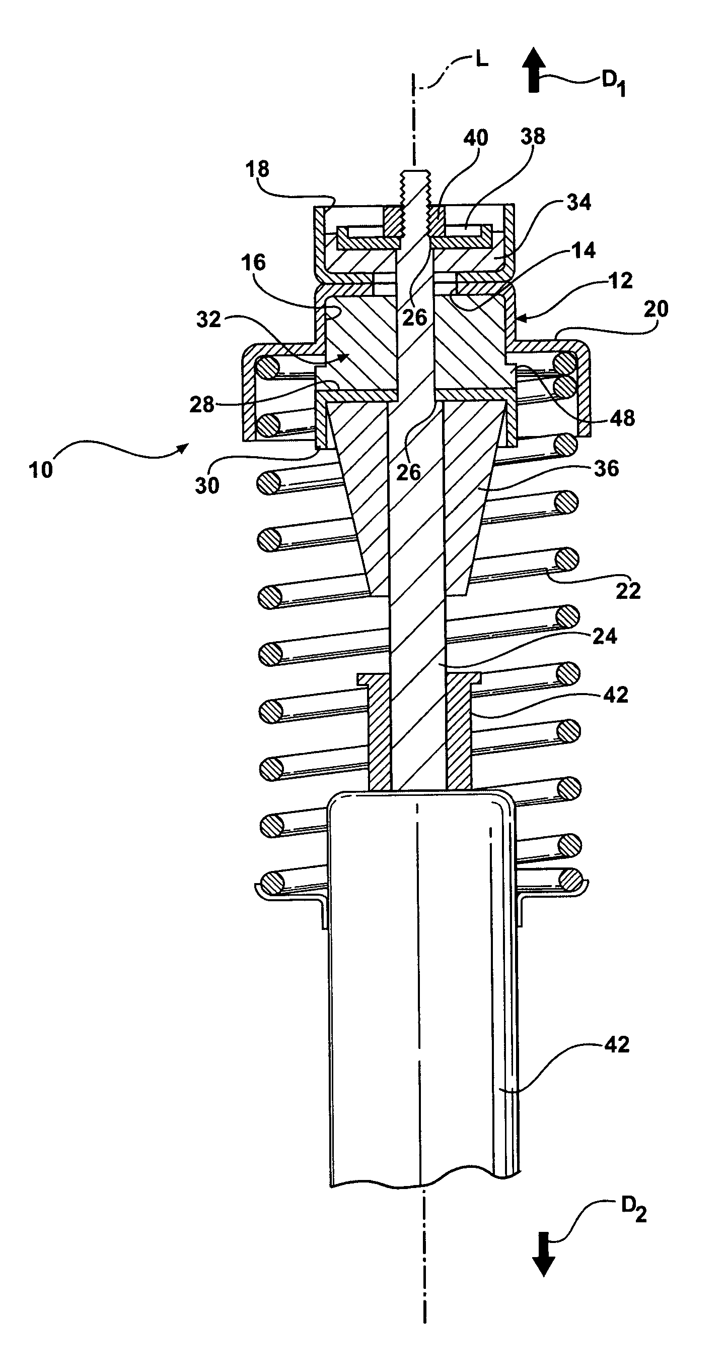
[0020] Referring to the Figures, wherein like numerals indicate like or corresponding parts throughout the several views, a mounting assembly in accordance with the subject invention is generally shown at 10 in FIG. 1. The mounting assembly 10 is shown in a rest state in this Figure. In the preferred embodiment, the mounting assembly 10 is for a wheel suspension system of a vehicle having a vehicle body (not shown). The wheel suspension system is only partially illustrated in the Figures. Wheel suspension systems for vehicles are well known in the art and as such will not be discussed in any greater detail. In addition, it should be appreciated by those skilled in the art that any suitable suspension system and any type of vehicle body could be used in conjunction with the subject invention.

[0021] The mounting assembly 10 includes a support structure 12 having an aperture 14. The support structure 12 is preferably a stamped piece of metal configured to define a number of different ...


PUM

PropertyMeasurementUnit
Forceaaaaaaaaaa
Elastomericaaaaaaaaaa
Widthaaaaaaaaaa

Abstract

A mounting assembly for a wheel suspension system of a vehicle. The mounting assembly includes a support structure mounted to the vehicle body. A piston rod, along with a plate, is displaceable relative to the support structure along a line of travel. An insulator is disposed between the support structure and the plate for coupling the piston rod to the support structure. The insulator has a first portion defining a first resistance for isolating the displacement of the piston rod and the plate during an application of a first force which compresses the first portion only. The insulator also has a second portion defining a second resistance, with the second resistance being greater than the first resistance, for limiting the displacement of the piston rod and the plate during an application of a second force wherein the second force is greater than the first force such that both the first and second portions are compressed.

Description

BACKGROUND OF THE INVENTION [0001] 1. Field of the Invention [0002] The subject invention relates to a mounting assembly for a wheel suspension system of a vehicle wherein the mounting assembly has an insulator for isolating and / or translating movement of the wheel suspension system. [0003] 2. Description of Related Art [0004] Mounting assemblies for wheel suspension systems of vehicles are well known in the art. Examples of such mounting assemblies are shown in U.S. Pat. Nos. 4,434,977; 4,478,396; 5,248,134; 5,330,166; 5,975,505; 6,076,794; and 6,260,835. Each of these mounting assemblies include a rigid support structure mounted to a chassis or frame of a vehicle. A piston rod extends from the wheel suspension system through the support structure. One or more insulators couple the piston rod to the support structure and allow for small relative movement of the piston rod to the support structure. The insulators also isolated the vibrations of the piston rod during an application o...

Claims


Application Information

Patent Timeline
IPC IPC(8): B60G13/00B60G15/06F16F7/00F16F9/54F16F9/58
CPCB60G13/003B60G15/067B60G2200/46B60G2202/312B60G2204/124B60G2204/128F16F9/58B60G2204/43B60G2204/44B60G2204/4502B60G2204/61B60G2500/20F16F9/54B60G2204/41
Inventor HUPRIKAR, ANANDMITCHELL, NATHANIEL
Owner BASF CORP
Why Eureka
Try Eureka