Linear actuator capable of low-speed driving

a low-speed driving, actuator technology, applied in the direction of dynamo-electric converter control, gearing, magnetic bodies, etc., can solve the problems of actuators, actuators, actuators, etc., and achieve the effect of simple and inexpensiv

Active Publication Date: 2005-01-20
SMC CORP
View PDF3 Cites 26 Cited by
  • Summary
  • Abstract
  • Description
  • Claims
  • Application Information

AI Technical Summary

Benefits of technology

[0012] Thus, the present invention provides a simple, inexpensive linear actuator which is capable of controlling the displacement of the movable body by regulating the amount of electric energy applied without the necessity of detecting the displacement of the movable body with a displacement sensor or controlling the displacement of the movable body by feedback control in response to the detected value.

Problems solved by technology

Consequently, said movable body moves at a high speed and produces noise when it collides violently against the stroke end.
However, this poses a problem with durability and dusting.
However, this method needs a displacement sensor and a complex control circuit, which inevitably makes the actuator larger and the control unit more complex.

Method used


Image

  • Linear actuator capable of low-speed driving
  • Linear actuator capable of low-speed driving
  • Linear actuator capable of low-speed driving

Examples


Embodiment Construction

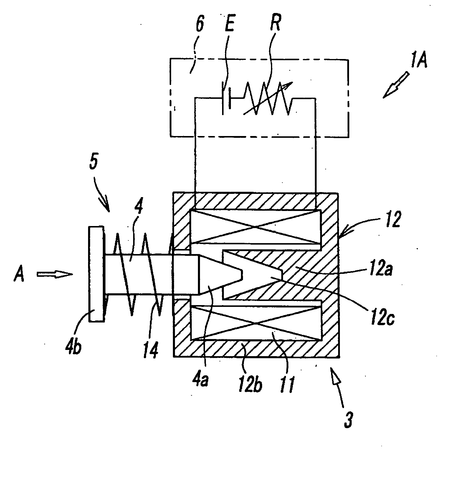
[0023]FIG. 1 is a schematic sectional view showing the linear actuator pertaining to the first embodiment of the present invention. The linear actuator 1A consists of an electromagnetic unit 3, which generates electromagnetic force in response to the amount of electric energy applied, a movable body 4, which is displaced linearly in the direction of arrow A by the magnetic thrust force produced by the electromagnetic unit 3, a spring means 5, which applies a force to the movable body 4 in the direction opposite to the direction A of the thrust force, and a control apparatus 6, which controls the displacement of the movable body 4 by regulating the amount of electric energy applied to the electromagnetic unit 3.

[0024] Said electromagnetic unit 3 consists of an exciting coil 11 and a core 12, which generates magnetic force as the exciting coil 11 is energized. The core 12 consists of an inner core 12a and an outer core 12b, which encloses the inner core 12a and said exciting coil 11....


PUM

PropertyMeasurementUnit
magnetic forceaaaaaaaaaa
voltageaaaaaaaaaa
spring forceaaaaaaaaaa

Abstract

Disclosed herein is a simple, inexpensive linear actuator which is capable of controlling the displacement of the movable body by regulating the amount of electric energy applied without the necessity of detecting the displacement of the movable body with a displacement sensor or controlling the displacement of the movable body by feedback control in response to the detected value. The linear actuator comprises an electromagnetic unit which generates magnetic force in response to the amount of electric energy applied, a movable body which is displaced linearly by magnetic force as thrust force which is supplied from the electromagnetic unit, a spring means which applies a spring force to the movable body in the direction opposite to the direction of said thrust force, and a control apparatus which controls the amount of electric energy to be applied to said electromagnetic unit, wherein said control apparatus is so constructed as to control the rate of displacement of said movable body in response to the amount of electric energy applied, with voltage or current applied to said electromagnetic unit varying from that which generates a thrust force balancing with said spring force.

Description

BACKGROUND OF THE INVENTION [0001] 1. Field of the Invention [0002] The present invention relates to a linear actuator which displaces a movable body linearly with electromagnetic force. More specifically, the present invention relates to a linear actuator capable of driving said movable body at low seeds. [0003] 2. Description of the Related Art [0004] There has long been known a linear actuator which drives a load by displacing a movable body linearly with electromagnetic force. The linear actuator of this type usually consists of an exciting coil, a core which generates electromagnetic force when the exciting coil is energized, and a movable body which is displaced by electromagnetic force as thrust force which is supplied from said core. [0005] The linear actuator mentioned above is usually so constructed as to be driven with a large thrust force in order that said movable body is displaced surely and stably against load and sliding resistance. Consequently, said movable body mo...

Claims


Application Information

Patent Timeline
Patent Type & Authority Applications(United States)
IPC IPC(8): F16H49/00H01F7/13H01F7/16H01F7/18H02K33/02H02K41/03
CPCH01F7/13H01F7/1607H02K41/03H02K33/02H01F7/1844
Inventor YAJIMA, HISASHIFUJIWARA, NOBUHIROITOU, SATORU
Owner SMC CORP
Why Eureka
Try Eureka