Eureka AIR delivers breakthrough ideas for toughest innovation challenges, trusted by R&D personnel around the world.

Multi-lamp actuating facility

Inactive Publication Date: 2005-01-20
MANIV ENERGY CAPITAL +1
View PDF5 Cites 7 Cited by
  • Summary
  • Abstract
  • Description
  • Claims
  • Application Information

AI Technical Summary

Benefits of technology

[0013] The primary objective of the present invention is to provide a lamp actuating facility for evenly and uniformly driving or actuating a number of light tubes or lamps of such as liquid crystal display (LCD) light devices or display panels.

Problems solved by technology

When a number of lamps are installed in the larger LCD display panels, a single transformer or driving or actuating circuit is not so effective on performance to actuate or drive two or more discharge lamps that are coupled parallel with each other.
For example, the impedances of the discharge lamps may be different from each other, and may seriously influence the flowing of the electricity through the discharge lamps; i.e., the electricity may not be evenly flown through the discharge lamps, such that the discharge lamps may not be suitably driven or actuated or energized.
When the electric current is less than the required amount, the discharge lamps may not be suitably driven or actuated or energized to the required brightness, and the brightness in different portions or areas of the larger LCD display panels may be different from each other, and may seriously decrease the uniformity of the display panels.
On the contrary, when the electric current is greater than the predetermined amount, the discharge lamps may be over-energized and the working life of the discharge lamps may be greatly decreased.
In addition, the characteristics of the discharge lamps may be changed any time, such that the electricity may not be used to evenly energize various discharge lamps.
Furthermore, when the discharge lamps are initialized, various kinds of strong interferences, noises, abrupt waves, may be generated, and may directly or indirectly affect the normal operation of peripheral facilities of the display panels.
The higher voltage is applied, the higher electromagnetic interference may be generated, and thus may injure the users and the others.
In addition, the discharge lamps of the typical LCD display panels may normally generate flashes that people may not be easily conscious of and that may hurt people or may easily fatigue people or users.

Method used


Image

  • Multi-lamp actuating facility
  • Multi-lamp actuating facility
  • Multi-lamp actuating facility

Examples


Embodiment Construction

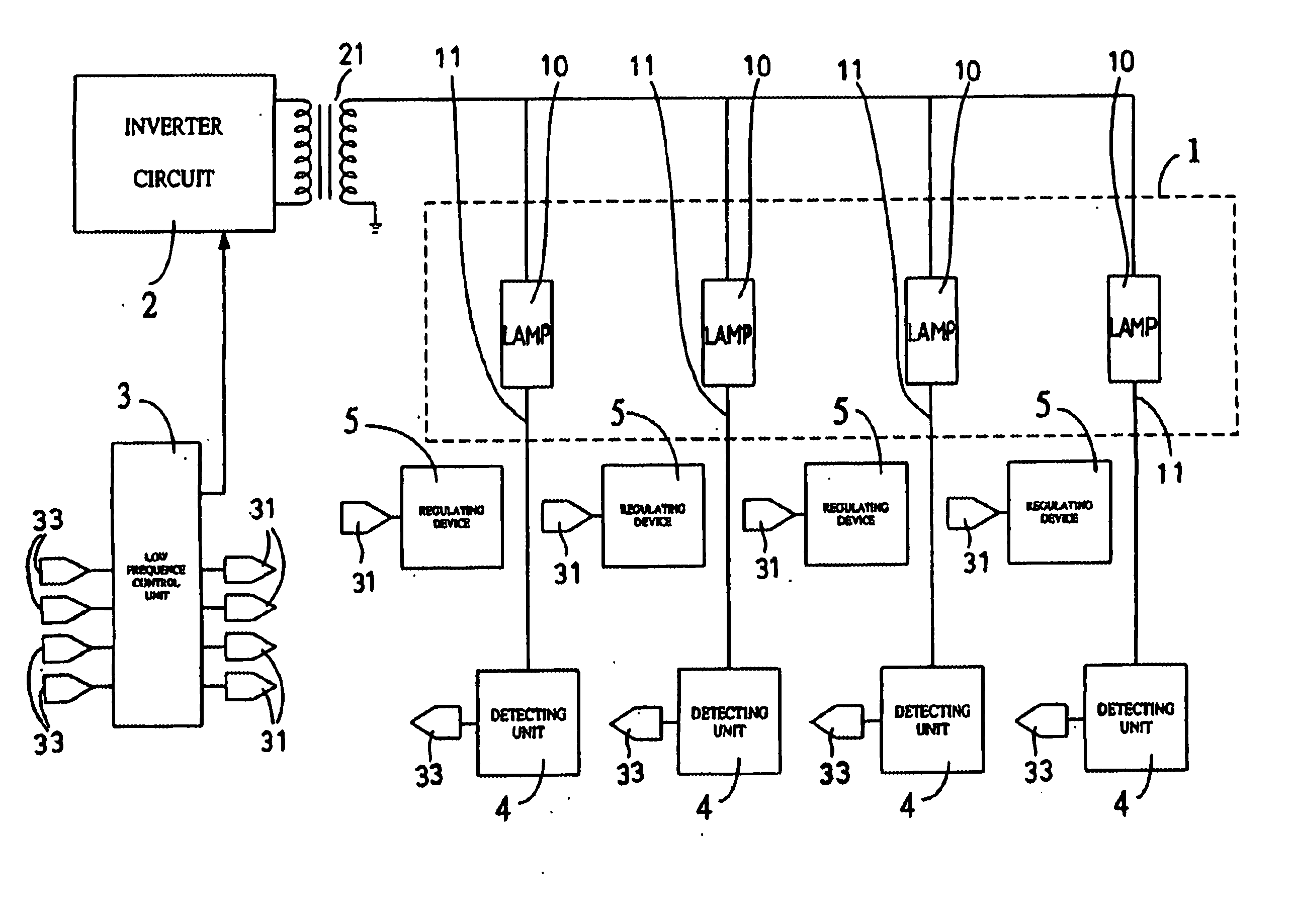
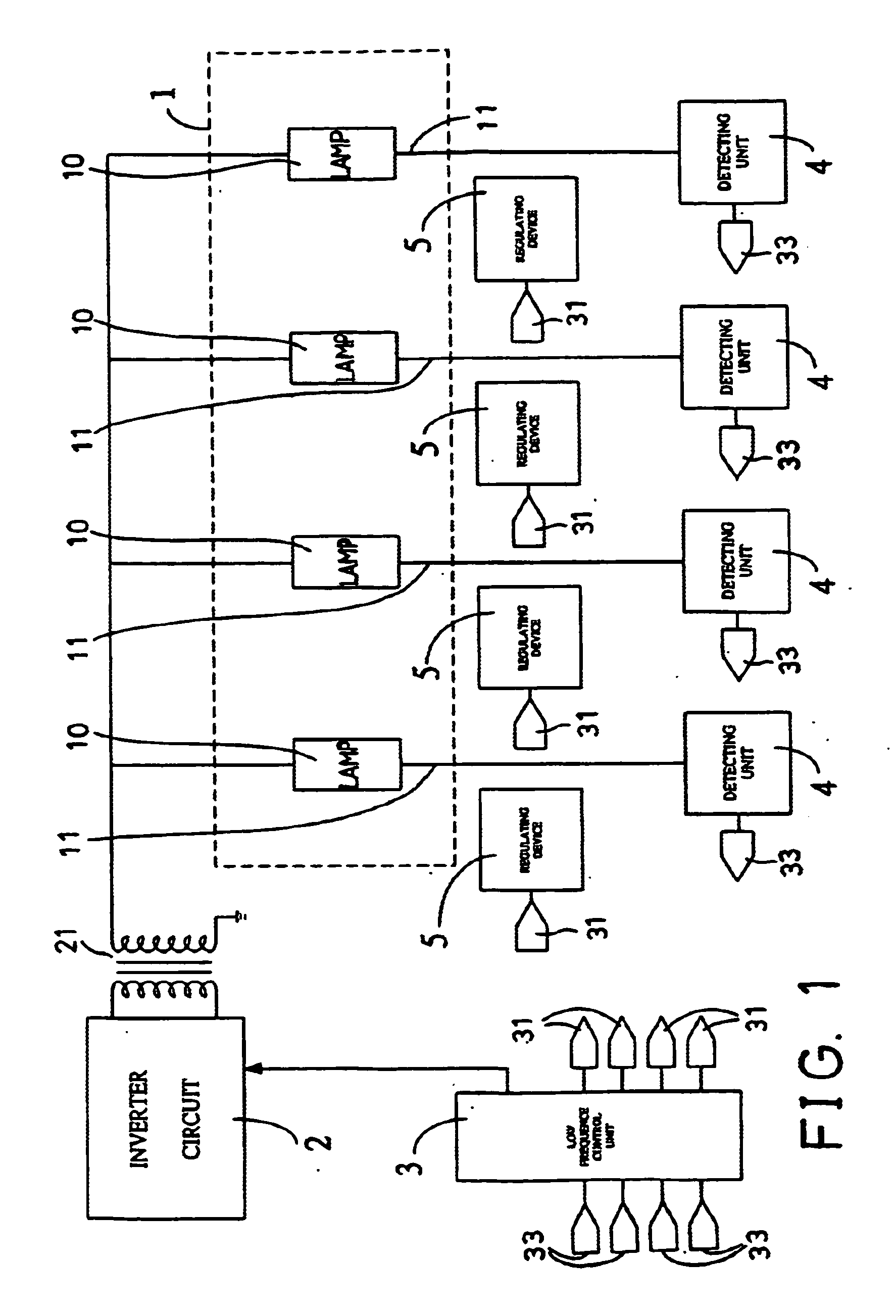
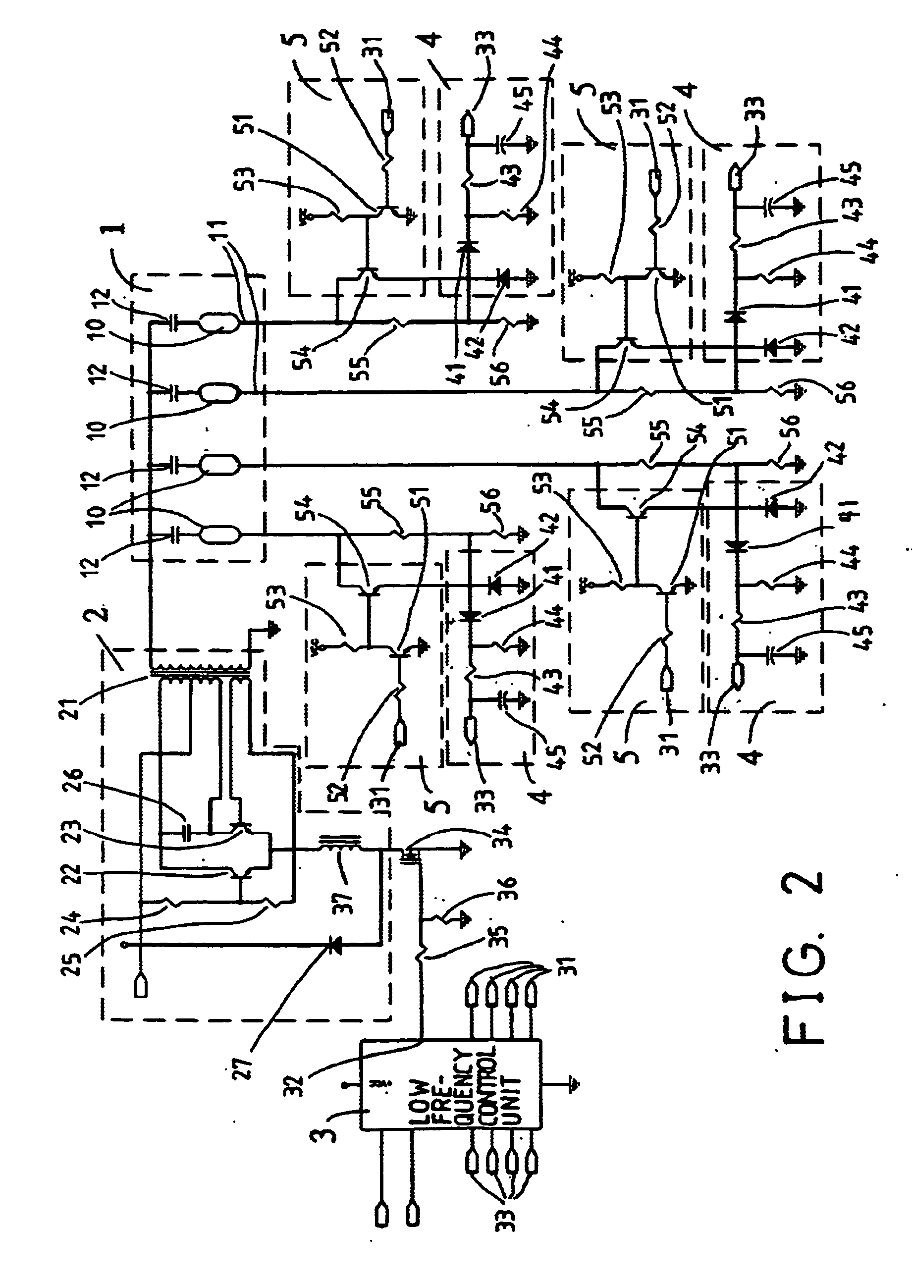
[0025] Referring to the drawings, and initially to FIG. 1, a lamp actuating facility in accordance with the present invention comprises a light device 1 including one or more lamps 10 coupled parallel to each other, and an inverter circuit 2 including a transformer 21 coupled to the lamps 10 of the light device 1, for converting direct current (DC) to alternate current (AC), in order to energize the lamps 10 of the light device 1.

[0026] A low frequency control unit 3 is coupled to the inverter circuit 2, for setting the average value of the effective current at the output terminals 11 of the lamps 10 of the light device 1, in order to control or actuate or drive the inverter circuit 2 to suitably provide the electricity to the lamps 10 of the light device 1 in predetermined period, and thus to suitably energize the lamps 10 of the light device 1.

[0027] One or more current detecting units 4 are coupled to the output terminals 11 of the lamps 10 of the light device 1, to detect or o...


PUM


Abstract

A lamp actuating device includes a number of lamps each having an output terminal, an inverter circuit coupled to the lamps to convert electric power and to energize the lamps, a low frequency control unit coupled to the inverter circuit, to set an average current value at the output terminals of the lamps and to control the inverter circuit, a number of current detecting units coupled between the lamps and the low frequency control unit to obtain and send the average current value at the output terminals of the lamps to the low frequency control unit. A number of regulating devices are coupled between the lamps and the low frequency control unit respectively, to control electric power through the lamps, and to maintain each of the lamps at the average current value.

Description

BACKGROUND OF THE INVENTION [0001] 1. Field of the Invention [0002] The presented invention relates to a light tube or lamp actuating facility, particularly to a lamp actuating facility for evenly or uniformly driving or actuating a number of light tubes or lamps such as liquid crystal display (LCD) light devices or display panels. [0003] 2. Description of the Prior Art [0004] Typical LCD display panels employ various kinds of discharge lamps, such as cold cathode fluorescent lamps (CCFL) as the backlight source for the display panels, and employ an inverter circuit to drive the discharge lamps. [0005] In larger LCD display panels, a number of lamps or light tubes are required to be provided and installed for providing the required brightness. When a number of lamps are installed in the larger LCD display panels, a single transformer or driving or actuating circuit is not so effective on performance to actuate or drive two or more discharge lamps that are coupled parallel with each ...

Claims


Application Information

Patent Timeline
IPC IPC(8): H05B41/282H05B41/392
CPCH05B41/392H05B41/2824
Inventor CHEN, MENDERCHAN, WOODYWANG, KEVIN
Owner MANIV ENERGY CAPITAL
Why Eureka
Eureka Blog
Learn More