High frequency pulse width modulation

Inactive Publication Date: 2005-01-20
LJM PROD INC
View PDF21 Cites 0 Cited by
  • Summary
  • Abstract
  • Description
  • Claims
  • Application Information

AI Technical Summary

Benefits of technology

[0015] The present invention achieves a further reduction in the amount of unwanted noise produced by electrical devices by providing an electrical device having pulse width modulation controls for providing a plurality of settings for operation of the device. The electrical device includes a system for selectively controlling the frequency of the pulse width modulation to provide a desired output operational intensity in response to a known input signal. The system includes a high frequency pulse width modulation signal module adapted to provide frequencies above the audible range of anticipated users of the device. By providing frequencies above the audible range of anticipated users, the unwanted noise produced by the electrical device is reduced or eliminated. The high frequency pulse width modulation signal module includes a signal converter. The signal converter receives the known input signal and converts that signal into a high frequency pulse width modulation output signal, which is then used to control the operational intensity of the device. The production of unwanted noise is reduced because the output signal has a frequency above the audible range of anticipated users of such electrical device.
[0019] The cooling device includes a system for selectively controlling the frequency of the pulse width modulation to provide a desired output cooling intensity in response to a known input signal. The system includes a high frequency pulse width modulation signal module adapted to provide frequencies above the audible range of anticipated users of such a personal computing device. The signal module includes a signal converter which receives the known input signal and converts that signal to a high frequency pulse width modulation output signal suitable to operate the cooling device at the desired output cooling intensity. Unwanted production of noise is reduced or eliminated because the output signal has a frequency above the audible range for anticipated users of the personal computing device.

Problems solved by technology

Excess and unwanted noise has become a problem throughout much of society.
Unwanted noise is often found to be distracting, thereby preventing people from giving their full concentration to tasks on which they attempt to keep their attention.
For example, a person attempting to give full attention to soft sounds such as the soft sounds associated with a quiet scene in a movie would find himself hindered in that regard if the movie could not be played without an associated and distracting unwanted noise accompanying the playing of the movie.
As another example, a person attempting to concentrate on tasks in a work environment may find efforts significantly hindered by unwanted noise, whatever its source.
A particularly widespread source of such unwanted noise is noise produced by electrical devices.
The heat dissipation issues associated with computing devices has lead the vast majority of such devices to include some sort of cooling device.
It is often the case that such cooling devices create unwanted noise.
By contrast, cooling fans such as those found in personal computers and notebook computers, as well as other computing devices, are notorious for creating a significant amount of unwanted noise.
Despite these improvements, a substantial amount of unwanted noise is still created by cooling fans.
Similarly, the use of cooling blowers to dissipate heat from computing devices is associated with generation of a significant amount of unwanted noise.
However a substantial amount of unwanted noise is still produced by cooling blowers.
For example, a medical device used during surgery that produces a significant amount of associated unwanted noise would naturally tend to hinder the concentration of the surgeon.

Method used


Image

  • High frequency pulse width modulation
  • High frequency pulse width modulation
  • High frequency pulse width modulation

Examples


Embodiment Construction

[0036] It will be understood by those skilled in the art that the present invention can be implemented in a number of different ways, within the scope of the claims appended hereto. A presently preferred embodiment of the invention will now be described below.

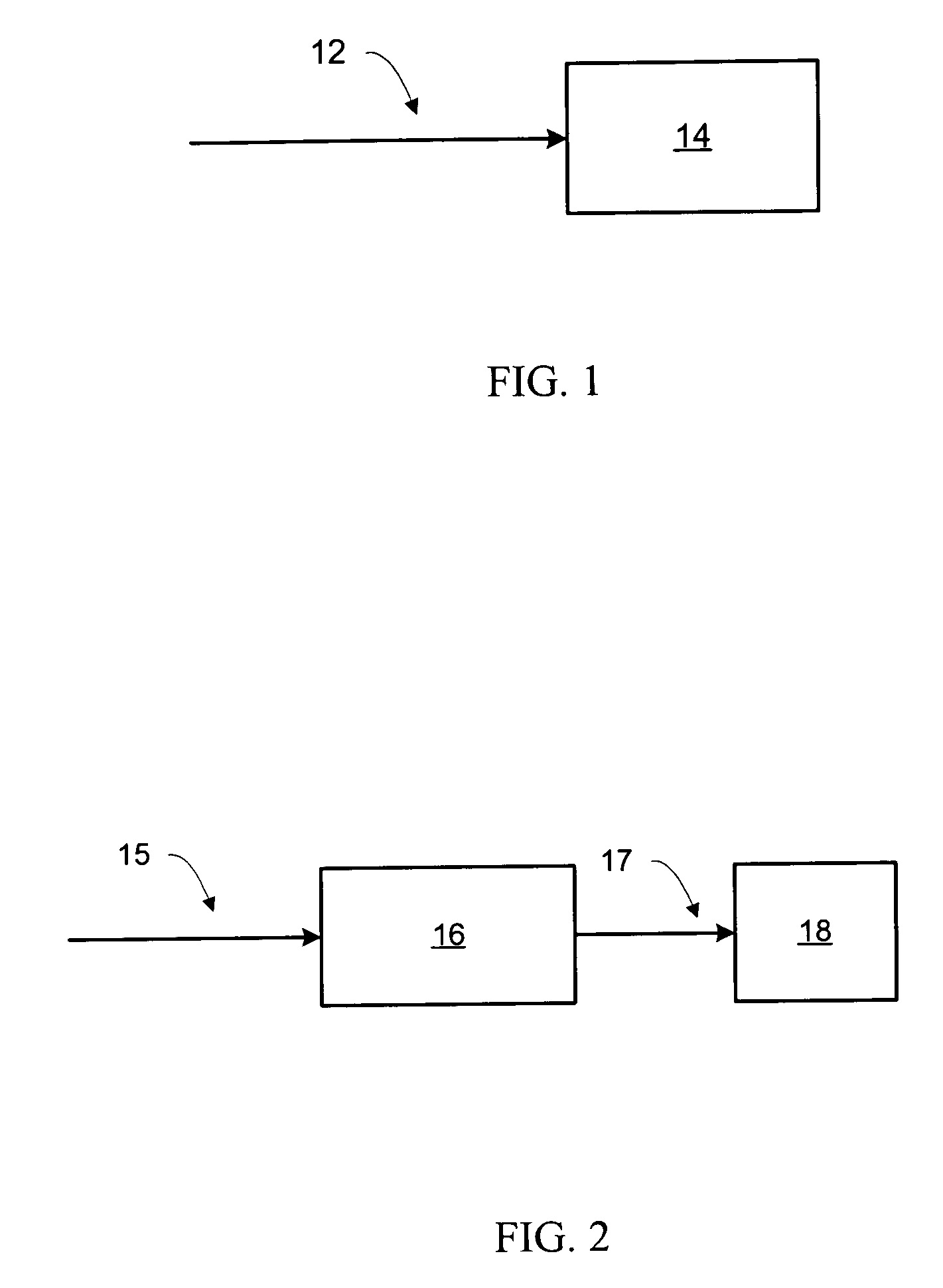
[0037] An electrical device 14 of the prior art is shown in FIG. 1. The operational intensity of electrical device 14 is controlled directly by DC input signal 12. Control is achieved by varying the DC input signal level. This approach to controlling operational intensity creates several problems. A significant amount of heat is generated which must be dissipated. Power inefficiencies occur and electronic and microelectronic components tend to be harmed by variation of voltage levels. As adoption of electronic and microelectronic components has become extremely widespread, the increased electronic and microelectronic failure rate associated with using DC input signals to directly control the operational intensity of electrical...


PUM


Abstract

An electronic device is provided that achieves a reduction in the amount of unwanted noise produced as a consequence of electrical switching associated with pulse width modulation. The electrical device includes pulse width modulation controls for providing a plurality of settings for operation of the device. The electrical device includes a system for selectively controlling the frequency of the pulse width modulation to provide a desired output operational intensity in response to a known input signal. The system includes a high frequency pulse width modulation signal module adapted to provide frequencies above the audible range of anticipated users of the device, thereby reducing or eliminating the production of unwanted noise associated with the operation of such an electrical device.

Description

[0001] Any references cited hereafter are incorporated by reference to the maximum extent allowable by law. To the extent a reference may not be fully incorporated herein, it is incorporated by reference for background purposes and indicative of the knowledge of one of ordinary skill in the art. BACKGROUND OF THE INVENTION [0002] 1. Field of the Invention [0003] The present invention relates generally to the field of noise reduction. [0004] 2. Description of Related Art [0005] Excess and unwanted noise has become a problem throughout much of society. Unwanted noise is often found to be distracting, thereby preventing people from giving their full concentration to tasks on which they attempt to keep their attention. [0006] For example, a person attempting to give full attention to soft sounds such as the soft sounds associated with a quiet scene in a movie would find himself hindered in that regard if the movie could not be played without an associated and distracting unwanted noise ...

Claims


Application Information

Patent Timeline
IPC IPC(8): G06F1/20H03C1/06
CPCG06F1/20
Inventor CHAKIR, CHAK
Owner LJM PROD INC
Why Eureka
Try Eureka