
Downhole clock

a technology of downhole clock and oscillation frequency, which is applied in the field of downhole clock, can solve the problems that the temperature sensitivity of oscillation frequency may not be adequate for the intended purpose, and achieve the effect of greater overall frequency stability

Active Publication Date: 2005-01-20
HALLIBURTON ENERGY SERVICES INC
View PDF7 Cites 43 Cited by
  • Summary
  • Abstract
  • Description
  • Claims
  • Application Information

AI Technical Summary

Benefits of technology

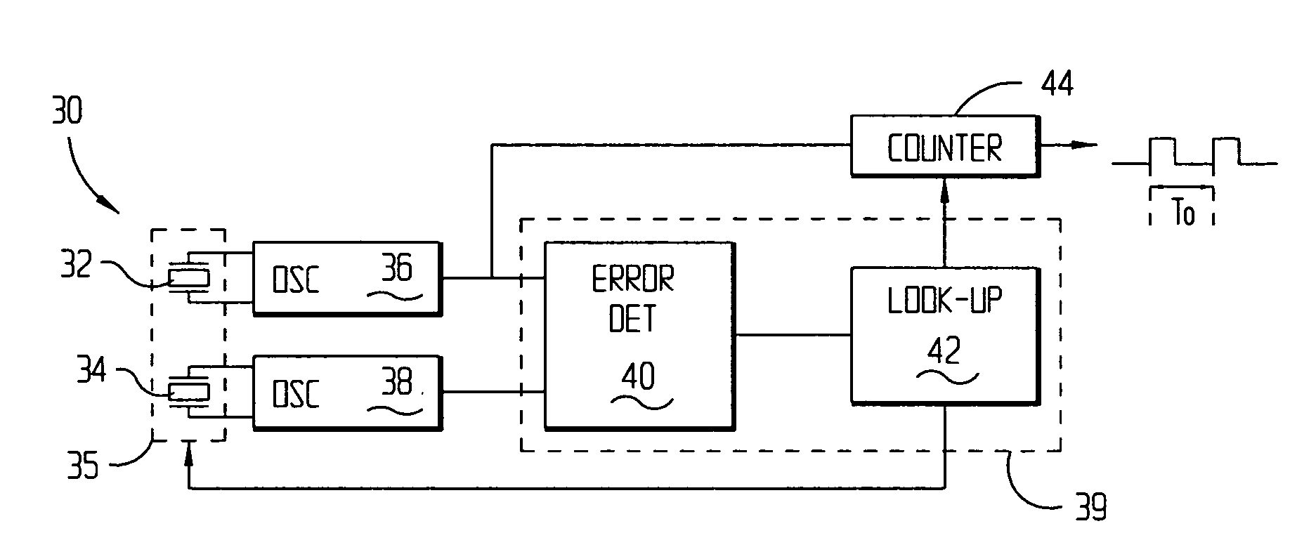
[0012] Accordingly, there is disclosed herein a method and apparatus for a downhole clock that is substantially insensitive to frequency deviations resulting from downhole temperatures. In some embodiments, the downhole clock may include at least two crystals. Using two crystals may be advantageous because each crystal's behavior, with respect to temperature, may be selected independent of the other. The crystals may include a first crystal whose frequency of oscillation varies only slightly with temperature variations and a second crystal whose frequency of oscillation varies within an amount greater than that of the first crystal. A relationship between the first and the second crystal's behavior with respect to temperature may be developed and stored. The relationship may be utilized to compensate the downhole clock for frequency variations stemming from downhole temperatures. Because the first and second crystals may be independently selected, the difference in their frequency behavior with respect to temperature may be selected to achieve a variance in temperature response that allows for greater overall frequency stability after correction.

Problems solved by technology

Because a single crystal is used, the temperature sensitivity of the oscillation frequencies may be inadequate for their intended purpose.

Method used


Image

  • Downhole clock
  • Downhole clock
  • Downhole clock

Examples


Embodiment Construction

[0012] Accordingly, there is disclosed herein a method and apparatus for a downhole clock that is substantially insensitive to frequency deviations resulting from downhole temperatures. In some embodiments, the downhole clock may include at least two crystals. Using two crystals may be advantageous because each crystal's behavior, with respect to temperature, may be selected independent of the other. The crystals may include a first crystal whose frequency of oscillation varies only slightly with temperature variations and a second crystal whose frequency of oscillation varies within an amount greater than that of the first crystal. A relationship between the first and the second crystal's behavior with respect to temperature may be developed and stored. The relationship may be utilized to compensate the downhole clock for frequency variations stemming from downhole temperatures. Because the first and second crystals may be independently selected, the difference in their frequency b...


PUM


Abstract

A downhole crystal-based clock that is substantially insensitive to the factors that may cause frequency deviation as a result of downhole temperature. The clock may include a plurality of crystals, where a first crystal may be more stable, with respect to temperature, than a second crystal. The crystals may be thermally coupled together so that they may have substantially the same temperature. An error detector may monitor the differences between the frequencies associated with each crystal and provide this information to a storage device. This information may be determined prior to deploying the clock downhole. When deployed downhole, the signal from the error detector may be interpreted in light of the information in the storage device to provide a temperature measurement of the two crystals. The downhole temperature measurement then may be used to reduce frequency deviations in the downhole clock that may result from downhole temperatures.

Description

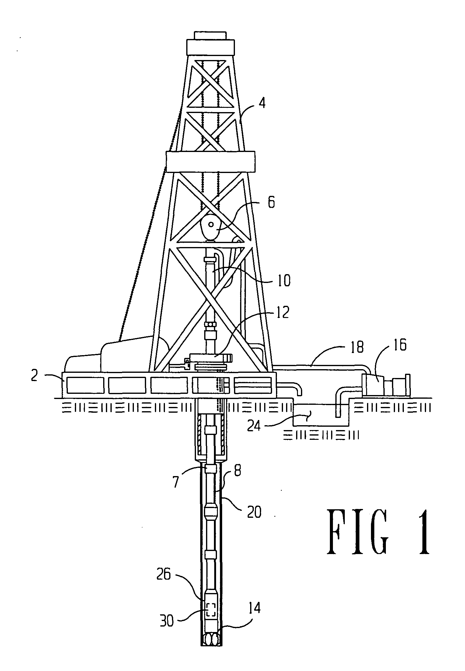
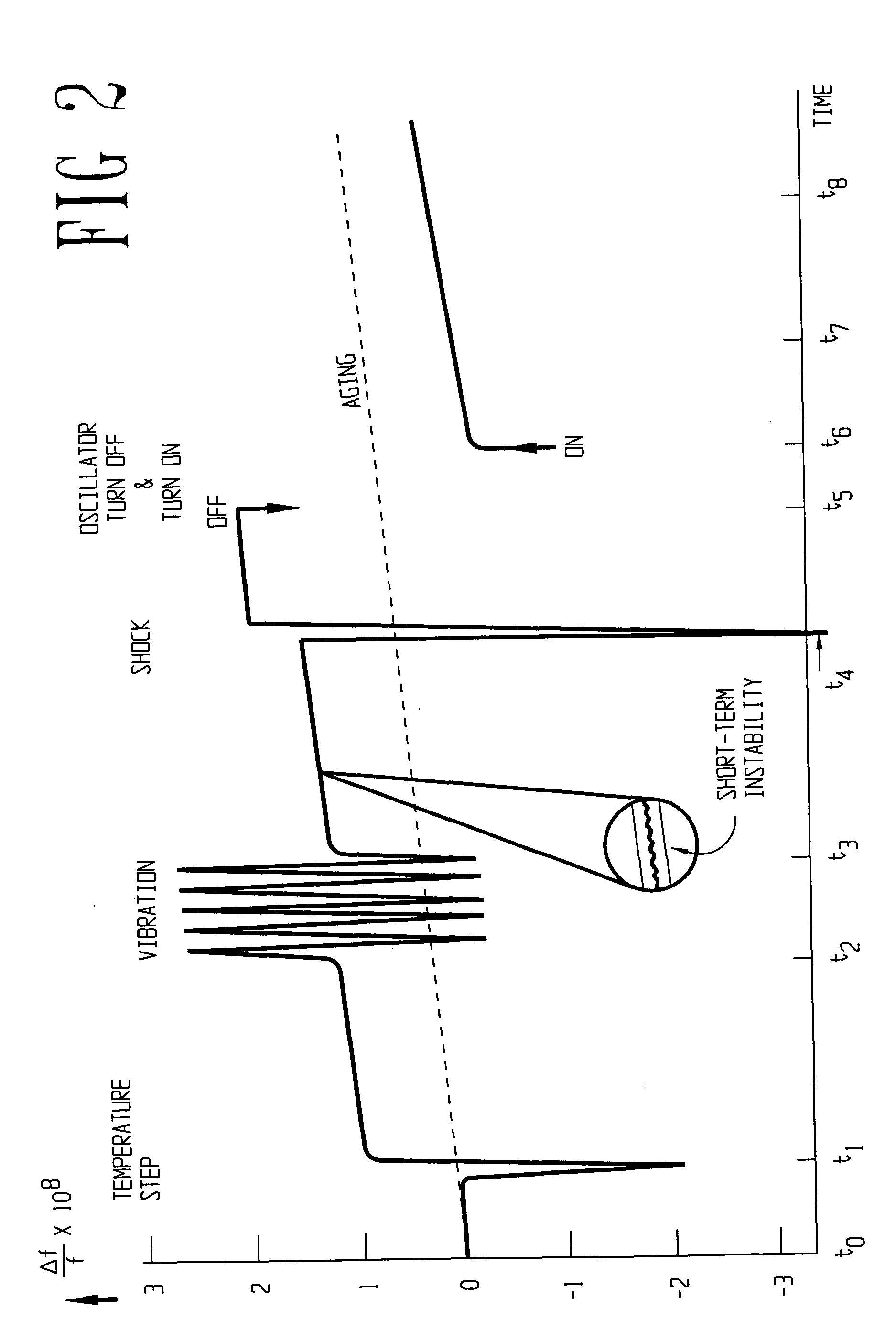
CROSS-REFERENCE TO RELATED APPLICATIONS [0001] This application is related to application Ser. No. 10 / 453,411, filed: Jun. 3, 2003 (attorney docket number 1391-38700) titled, “Method and System for Downhole Clock” which is incorporated by reference herein as if reproduced in full below.STATEMENT REGARDING FEDERALLY SPONSORED RESEARCH OR DEVELOPMENT [0002] Not applicable. BACKGROUND OF THE INVENTION [0003] 1. Field of the Invention [0004] The preferred embodiments relate to well logging. More particularly, the preferred embodiments relate to generating a downhole clock for improving data measurements taken during logging. [0005] 2. Description of the Related Art [0006] Modern petroleum drilling and production operations demand a great quantity of information relating to parameters and conditions downhole. Such information may include characteristics of the earth formations traversed by the wellbore, along with data relating to the size and configuration of the borehole itself. The co...

Claims


Application Information

Patent Timeline
IPC IPC(8): H03L1/02H03L1/04
CPCH03L1/04H03L1/022
Inventor YOUNG, DAVID J.ROBBINS, CARL A.LINYAEV, EUGENE
Owner HALLIBURTON ENERGY SERVICES INC
Learn More