Integrated alarm display in a process control network

a technology of process control network and alarm display, applied in the field of display of alarm conditions, can solve the problems of inability of conventional 4-20 ma devices to generate alarms pertaining to the operation capability of the device itself, and applications that are not configured to display other types of errors or alarms

Inactive Publication Date: 2005-01-20
FISHER-ROSEMOUNT SYST INC
View PDF9 Cites 70 Cited by
  • Summary
  • Abstract
  • Description
  • Claims
  • Application Information

AI Technical Summary

Benefits of technology

[0010] An alarm display and interface system for use in a process control network receives and displays different categories of alarms, including for example, device alarms and hardware alarms as well as traditional process alarms, on a single display in an integrated manner to enable an operator or other user to view, have access to and manipulate the alarms of different categories. The display and interface system

Problems solved by technology

These applications are not configured to display other types of errors or alarms, such as alarms associated with malfunctioning field devices or other hardware like controllers or input/output (I/O) devices.
However, it requires an experienced or knowledgeable operator to detect device or hardware problems from process alarms.
However, these 4 to 20 ma signals are limited in nature in that they are indicative of process measurements made by the device or of process control signals generated by the controller required to control the operation of the device during runtime.
As a result, the conventional 4-20 ma devices are incapable of generating alarms pertaining to the operational capability of the device itself.
As a result, alarms associated with these devices have generally not been available within process control systems.
However, there has been few if any display applications for displaying

Method used


Image

  • Integrated alarm display in a process control network
  • Integrated alarm display in a process control network
  • Integrated alarm display in a process control network

Examples


Embodiment Construction

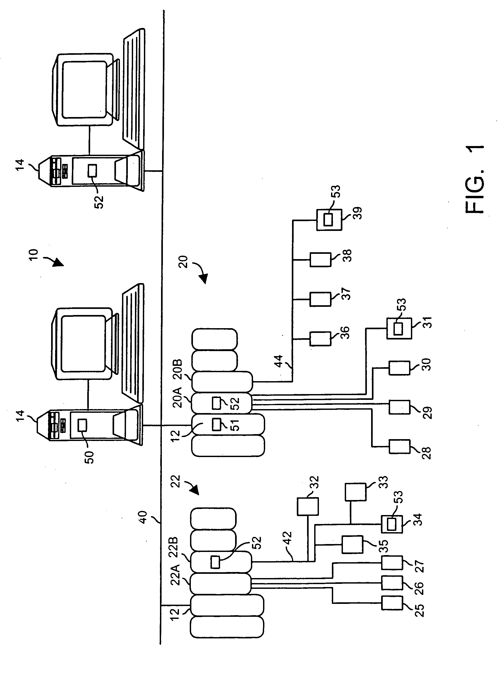
[0027] Referring now to FIG. 1, a process control network or system 10 includes one or more process controllers 12 connected to one or more host workstations or computers 14 (which may be any type of personal computer or workstation) and connected to banks of input / output (I / O) devices 20, 22 each of which, in turn, is connected to one or more field devices 25-39. The controllers 12, which may be, by way of example only, DeltaV™ controllers sold by Fisher-Rosemount Systems, Inc., are communicatively connected to the host computers 14 via, for example, an Ethernet connection 40 or other communication link. Likewise, the controllers 12 are communicatively connected to the field devices 25-39 using any desired hardware and software associated with, for example, standard 4-20 ma devices and / or any smart communication protocol such as the Fieldbus or HART protocols. As is generally known, the controllers 12 implement or oversee process control routines stored therein or otherwise associa...


PUM


Abstract

An alarm display and interface tool for use in a process control system receives and displays different categories of alarms, including for example, device alarms and hardware alarms as well as traditional process alarms, on a single display to enable an operator or other user to view and have access to these different categories of alarms. The display and interface tool may be used to filter the alarms that are displayed according to any number of categories, including the category of the alarm, the priority of the alarm, the status of the alarm, etc. so as to alternatively segregate or combine the tasks typically associated with operator, maintenance and engineer personnel. The tool may also be used to access each of the displayed alarms to obtain more information about any individual alarm.

Description

FIELD OF THE INVENTION [0001] The present invention relates generally to process control systems and, more particularly, to the display of alarm conditions within a process control system. DESCRIPTION OF THE RELATED ART [0002] Process control systems, like those used in chemical, petroleum or other processes, typically include one or more centralized process controllers communicatively coupled to at least one host or operator workstation and to one or more field devices via analog, digital or combined analog / digital buses. The field devices, which may be, for example valves, valve positioners, switches and transmitters (e.g., temperature, pressure and flow rate sensors), perform functions within the process such as opening or closing valves and measuring process parameters. The process controller receives signals indicative of process measurements made by the field devices and / or other information pertaining to the field devices, uses this information to implement a control routine ...

Claims


Application Information

Patent Timeline
IPC IPC(8): G05B19/05G06F3/14G05B23/02
CPCG05B23/0272
Inventor HAVEKOST, ROBERT B.SCHLEISS, TREVOR D.OTT, MICHAEL G.SCOTT, CINDYFLETCHER, J. CLINT
Owner FISHER-ROSEMOUNT SYST INC
Why Eureka
Try Eureka