Burst pulse circuit for signal lights and method

a pulse circuit and signal light technology, applied in the field of signal lights, can solve the problems of high efficiency, low power consumption of prior art flashing light devices, and high efficiency of prior art illumination means, and achieve the effect of low power consumption and low power consumption

Active Publication Date: 2005-01-20
TRAFCON INDS
View PDF21 Cites 19 Cited by
  • Summary
  • Abstract
  • Description
  • Claims
  • Application Information

AI Technical Summary

Benefits of technology

[0015] In another embodiment of the invention, a signal, such as a traffic directional or cautionary signal, e.g., a flashing speed limit, directional arrows, or verbal cues, i.e., “slow-down”, “turn right”, “detour,” is provided including one or more arrays of flashing lights. Each array of lights is arranged in electrical communication with a power supply that provides a pulse width modulated signal to drive the flashing of the arrays. Each light comprises a plurality of light emitting diodes having a first color and a first brightness wherein each of the flashing lights includes at least one superluminescent light emitting diode having a ma...

Problems solved by technology

However, each of these prior art illumination means has had its disadvantages.
In particular, prior art flashing light devices have not provided effective light output with low power consumption (i.e. high efficiency) at desirable high flash rates, and could not do so without severely sacrificing device power consumption and reliability of the light source.
Thus a problem in the prior art has been the inability to provide a reliable warning light having high brilliance with low power operation, and that is suitable for use in portable lightweight battery powered equipment.
However, they often are not able to come to full brightness and to then cool off to extinction (i.e. turn on and off) within the higher optimum flash rate frequencies for attracting attention.
Furthermore, because of the inherent thermal inertia of incandescent light sources (once turned sufficiently on to emit light, there is a significant delay in extinction to the off state), such light sources cannot provide flashes of relatively short duration, nor can such light sources provide adequate on-off contrast when operated at higher flash rates.
In addition, an incandescent flashing light with adequate intensity for outdoor use usually requires larger size batteries to compensate for the excessive power loss in the form of heat, thus rendering it impractical for applications requiring reasonably small size and light weight necessary for portability.
As a consequence, incandescent light sources are not suitable for use as warning lights at those flash rates and flash duration periods to which human visual perception is most sensitive but are constrained to use at lower frequencies and longer flash perio...

Method used


Image

  • Burst pulse circuit for signal lights and method
  • Burst pulse circuit for signal lights and method
  • Burst pulse circuit for signal lights and method

Examples


Embodiment Construction

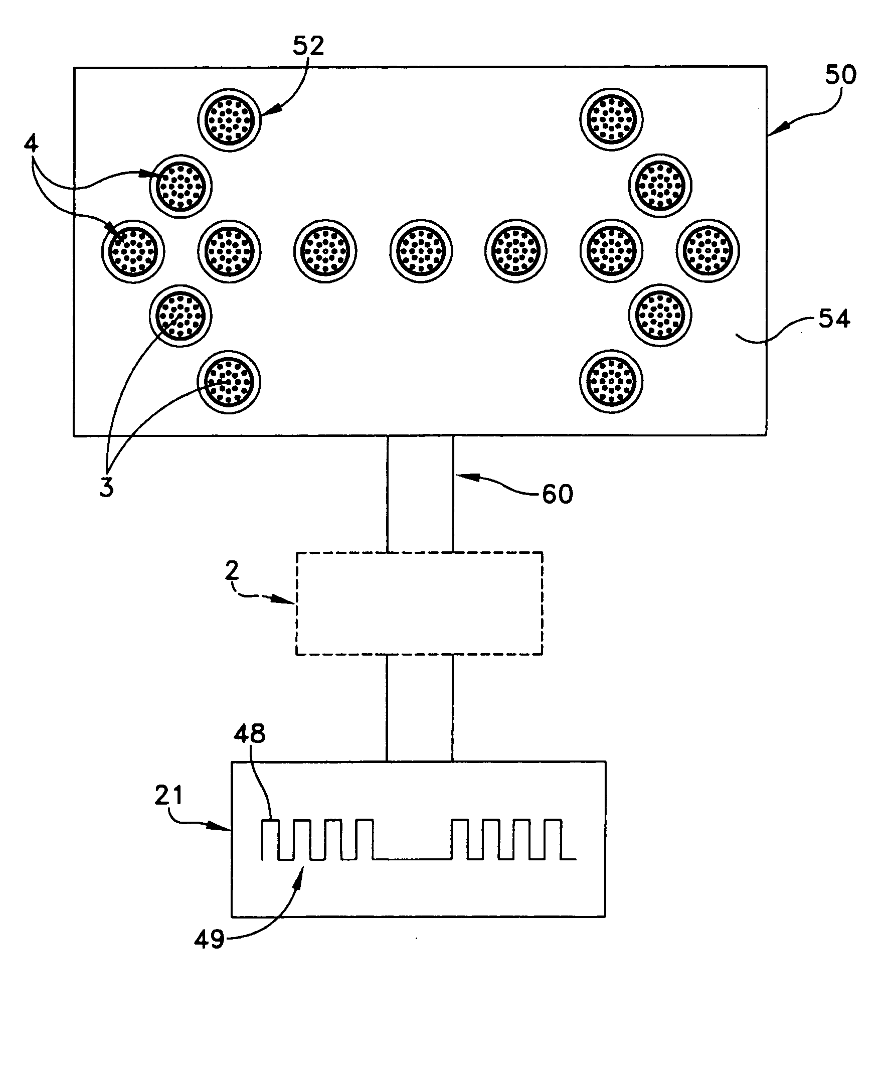
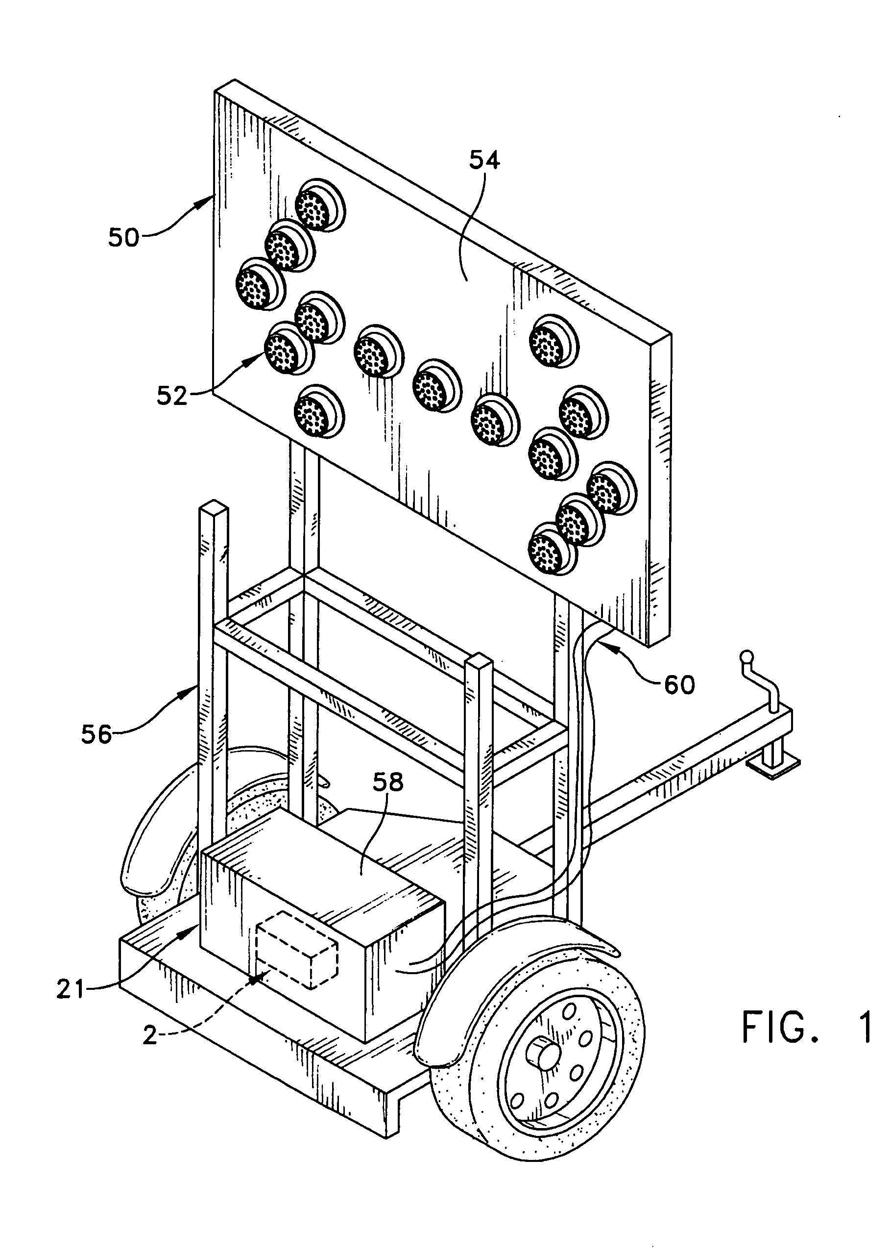
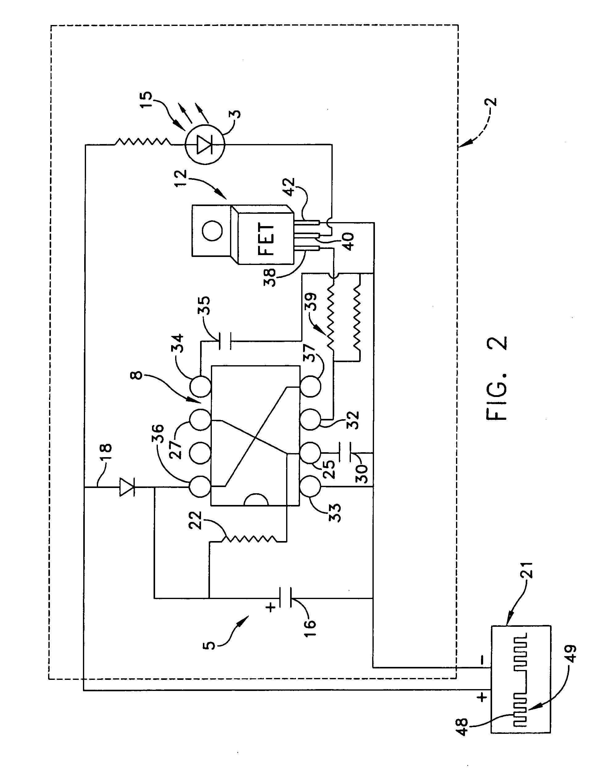
[0031] This description of preferred embodiments is intended to be read in connection with the accompanying drawings, which are to be considered part of the entire written description of this invention. The drawing figures are not necessarily to scale and certain features of the invention may be shown exaggerated in scale or in somewhat schematic form in the interest of clarity and conciseness. Terms concerning attachments, coupling and the like, such as “connected” and “interconnected,” refer to a relationship wherein structures, circuits, or circuit elements are electrically or mechanically secured or attached to one another either directly or indirectly through intervening structures, unless expressly described otherwise. The term “level” refers to a reference voltage or current that may or may not have a zero magnitude. In the claims, means-plus-function clauses are intended to cover the structures described, suggested, or rendered obvious by the written description or drawings ...


PUM


Abstract

A circuit is provided for over-driving a super-luminescent light emitting diode having a maximum forward continuous current rating. A power supply provides a pulse width modulated signal to an analog memory connected to the power supply and a pulse generator. The pulse generator includes a window comparator engaged with the analog memory, and is responsive to a portion of the pulse width modulated signal. A power driver that is controlled by the output of the pulse generator, is operably connected with the super-luminescent light emitting diode and with the power supply so as to energize the super-luminescent light emitting diode with a current that is above the maximum forward continuous current rating by between two and ten times that rated current. A signal is also provided along with a method of over-driving a super-luminescent light emitting diode. An inverter and timer are coupled to the pulse generator and an array of light emitting diodes that operate at time intervals determined by the timer that are wholly distinct from time intervals when the at least one super-luminescent light emitting diode is over-driven.

Description

[0001] This is a Continuation-in-part of U.S. patent application Ser. No. 10 / 617,280, filed Jul. 10, 2003.FIELD OF THE INVENTION [0002] The present invention generally relates to signal lights and, more particularly to signal lights including light emitting diodes. BACKGROUND OF THE INVENTION [0003] Flashing, i.e., intermittently or periodically illuminated, lights have long been used to provide visual warnings, and a considerable body of research has been compiled in the fields of physiology, psychology and engineering concerning human perception of flashing light (i.e. the ability of people to perceive and respond to flashing light). This field of study involves the study of psycho-visual or psycho-optical sensory phenomena. [0004] It is known in the art that certain factors may be applied to the provision of a flashing warning light for improving the visibility of a flashing light, that is, for making a flashing light visible at a greater distance, and for enhancing the probabili...

Claims


Application Information

Patent Timeline
CPCH05B33/0803H05B33/0842H05B33/0818H05B45/327H05B45/325
Inventor GALLAGHER, SHAWNJOHNSON, MATTHEWZINK, TIMOTHY
Owner TRAFCON INDS
Why Eureka
Try Eureka