Sensing apparatus

a technology of sensing apparatus and sensor, which is applied in the direction of magnetic measurement, printing, using electrical/magnetic means, etc., can solve the problems of cumbersome and impractical use as portable devices, inability to easily generate information related to written characters or shapes, and inability to use in natural writing positions, etc., to eliminate axial degeneracy, simple magnetic dipole, and simplest and cheapest magnetic field

Inactive Publication Date: 2005-01-20
THE TECHNOLOGY PARTNERSHIP PLC
View PDF3 Cites 50 Cited by
  • Summary
  • Abstract
  • Description
  • Claims
  • Application Information

AI Technical Summary

Benefits of technology

[0025] Simple magnetic dipole. This has the advantage of being the simplest and cheapest magnetic field to apply to a spherical object. Additionally the magnetic field strength for a given size of spherical object will be the highest for this form of magnetisation.
[0026] Curved magnetic dipole. This has the advantage of eliminating axial degeneracy associated with a simple dipole. This means that the case where the spherical object can rotate about the magnetic axis, and so eliminate any change in magnetic field measured by the sensors, is eliminated.
[0027] Multiple magnetic domains—quadrupole and multiple pole. Whilst creating a spherical object with 4 or multiple poles is more complicated than creating a single dipole (straight or curved) this magnetic field pattern has the advantage of providing finer resolution of position of a spherical object.
[0029] In the latter case, for the ball to be able to rotate, it is necessary that it is held within a bearing that allows it to rotate freely. The ball can then respond to any applied rotational disturbance. The bearing may additionally require some form of static or hydrodynamic fluid lubrication to aid smooth and / or reliable operation.
[0033] Accurate machining of the ball housing can be used to fix this, but since in many cases the housing can actually wear during use, it would be advantageous to separate the ball and its housing from the sensor assembly. This will allow easy replacement of worn parts.

Problems solved by technology

Many of these cannot be used in a natural writing position and so cannot easily generate information related to written characters or shapes which can be captured and further analysed.
Those devices which can be held in a natural writing position, such as light pens or digitising tablets, can only be used to a generate information by using two distinct parts, whether the parts are tethered or wireless, and therefore they are expensive, cumbersome and impractical to use as portable devices, i.e. when the user is traveling.

Method used


Image

  • Sensing apparatus
  • Sensing apparatus
  • Sensing apparatus

Examples


Embodiment Construction

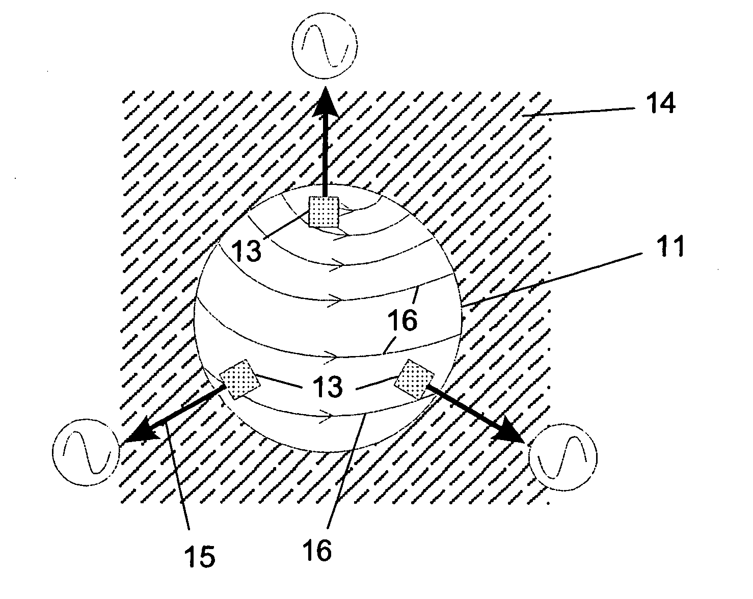
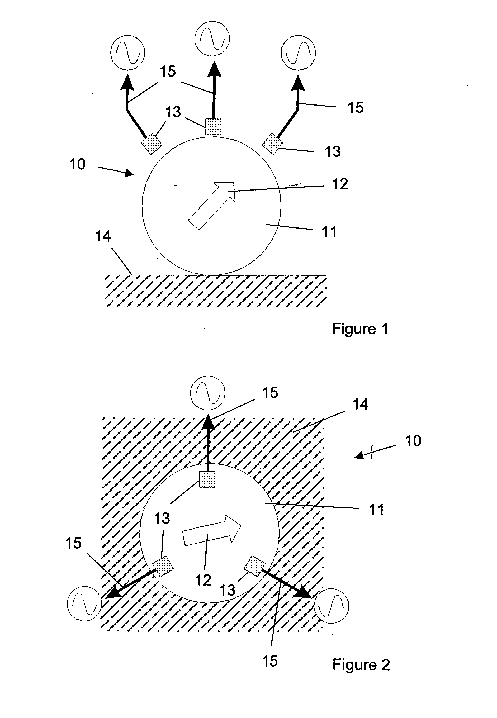
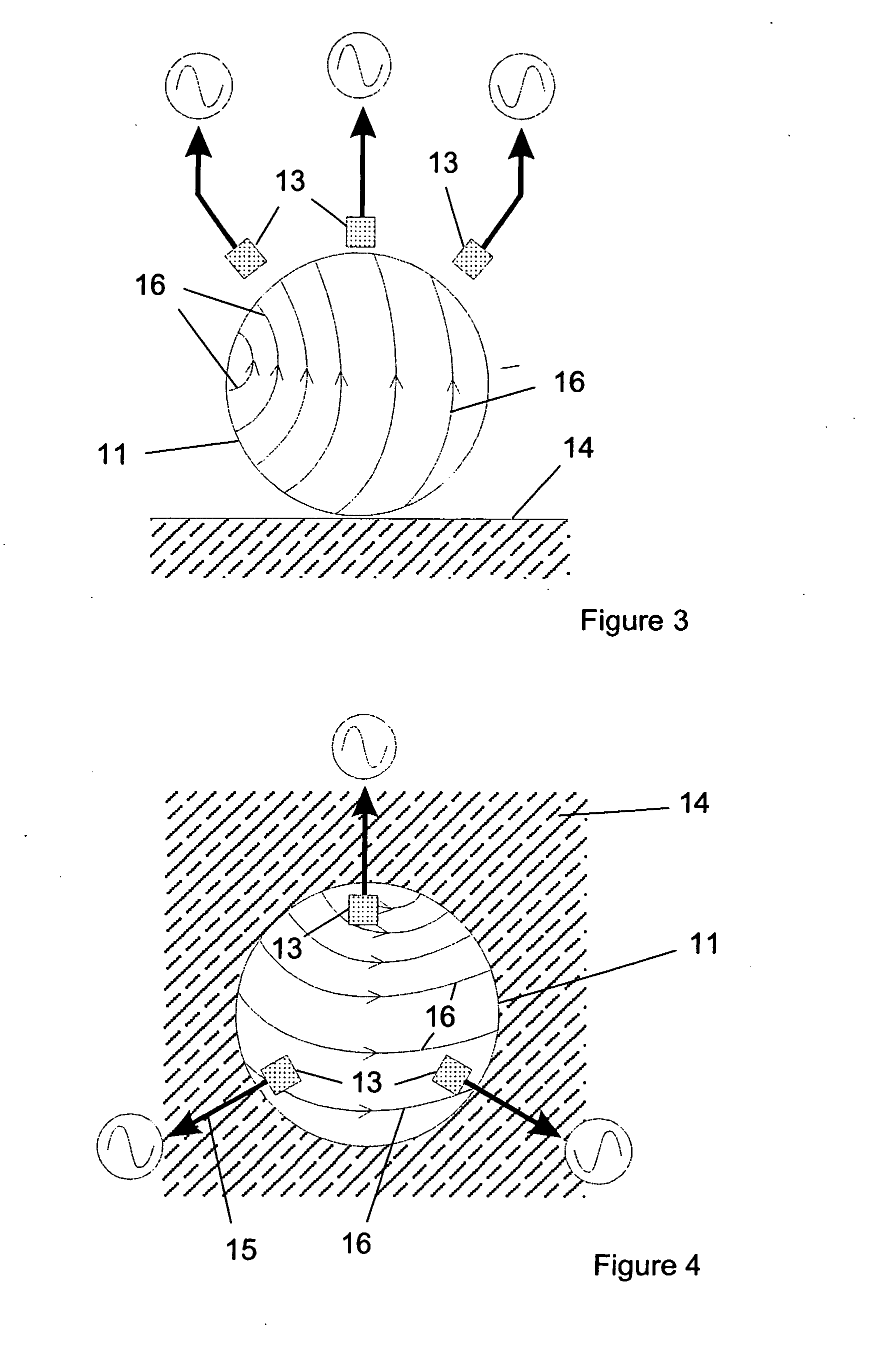
[0066] In FIG. 1, the sensing apparatus 10 comprises a spherical ball 11 which is magnetised with a dipole 12. The ball is typically 700-1000 μm in diameter. The ball is retained in a housing (not shown) of typical wall thickness of 100 μm in which three magnetic field sensors 13 are mounted. The sensors 13 are approximately 200 μm from the surface of the ball 11. In use, the ball 11 is placed in contact with surface 14 such that, as the body is moved relative to the surface, the ball 11 rotates relative to the magnetic field sensors 13. In this way, the orientation of the dipole changes, thereby altering the magnetic field around the ball. This alteration is then detected by the sensors 13. The sensors 13 convert the detected field change into continuously variable output signals 15.

[0067] The magnetic field sensors 13 are, in this example, thin film transducers. In this example three sensors are preferred to determine the motion of the ball 11. In the description of the remaining...


PUM


Abstract

A sensing apparatus for detecting a translation of a body relative to a surface, the apparatus comprising: a rolling component for contact, in use, with the surface, the rolling component being retained by, and able, in use, to rotate independently of the body; one or more indicator means associated with the rolling component and rotatable therewith; and one or more transducers for producing one or more signals in response to a rotation of the indicator means relative to the one or more transducers wherein, in use, the rolling component rolls upon the surface in response to a relative translation of the body to the surface, thereby causing the positional orientation of the indicator means to change with respect to the transducers.

Description

CROSS-REFERENCE TO RELATED APPLICATIONS [0001] The present application is the U.S. National Stage filing under 35 U.S.C. § 371 of International Application No. PCT / GB02 / 04817 filed Oct. 24, 2002 and published on May 1, 2003 as Publication No. WO 03 / 036560, which claims priority to UK Application No. 0125529.8, filed Oct. 24, 2001.BACKGROUND OF THE INVENTION [0002] This invention relates to a sensing apparatus and, in particular, a sensing apparatus for detecting the translation of a body relative to a surface. [0003] Prior known sensors have either detected movement per se or specific movement in one or more directions. Such sensors have been incorporated in hand-held devices. [0004] Well known hand-held input devices which allow the user of such devices to interact with computer generated environments include touch screens, track balls, mice, joysticks, gloves, digitising tablets with styli and light pens interacting on electronic write boards. A number of these are designed princi...

Claims


Application Information

Patent Timeline
Patent Type & Authority Applications(United States)
IPC IPC(8): B43K29/093B43K7/00B43K29/08G06F3/0354G06F3/041
CPCG06F3/03546
Inventor MIKULIN, DOMINIC JOSEFJANSE VAN RENSBURG, RICHARD WILHELMSELBY, ROBERT GORDON MAURICE
Owner THE TECHNOLOGY PARTNERSHIP PLC
Why Eureka
Try Eureka