Sliding-window based signal monitoring

a sliding window and signal monitoring technology, applied in the direction of transmission monitoring, line-transmission, line-transmission details, etc., can solve the problems of difficult to adapt the signal monitor to system or application changes implying supervision of signals with other characteristics, the general detection mechanism capable of handling different types of signals under various conditions is normally very complex and requires extensive data processing, and the detection time latency is generally far too high to be acceptable, so as to reduce the overall complexity and the detection time latency. , to increas

Inactive Publication Date: 2005-01-20
TELEFON AB LM ERICSSON (PUBL)
View PDF4 Cites 10 Cited by
  • Summary
  • Abstract
  • Description
  • Claims
  • Application Information

AI Technical Summary

Benefits of technology

It is another object of the invention to provide a monitoring mechanism that offers a flexible degree of error correction redundancy for handling possible metastability situations.
Yet another object of the invention is to devise a monitoring mechanism that can be formed as distributed detection algorithm and parallelized so as to reduce overall complexity and detection time latency.
It is furthermore beneficial if the signal monitoring mechanism reduces the need for oversampling, thus considerably increasing the operation frequency range.

Problems solved by technology

This generally means that the signal monitors are customized for signals with certain characteristics, thus making it difficult to adapt the signal monitors to system or application changes that imply supervision of signals with other characteristics.
General detection mechanisms that are capable of handling different types of signals under various conditions are normally very complex and require extensive data processing.
In high-frequency applications, however, the detection time latency is generally far too high to be acceptable.
For high-frequency signals, there is simply not enough time for a complex detection mechanism to detect a signal failure in just a few clock cycles.
However, when the frequency of the monitored signal reaches higher and higher levels, it may not be possible to generate a high-frequency sample clock for oversampling purposes, at least not to a reasonable cost.

Method used


Image

  • Sliding-window based signal monitoring
  • Sliding-window based signal monitoring
  • Sliding-window based signal monitoring

Examples


Embodiment Construction

Throughout the drawings, the same reference characters will be used for corresponding or similar elements.

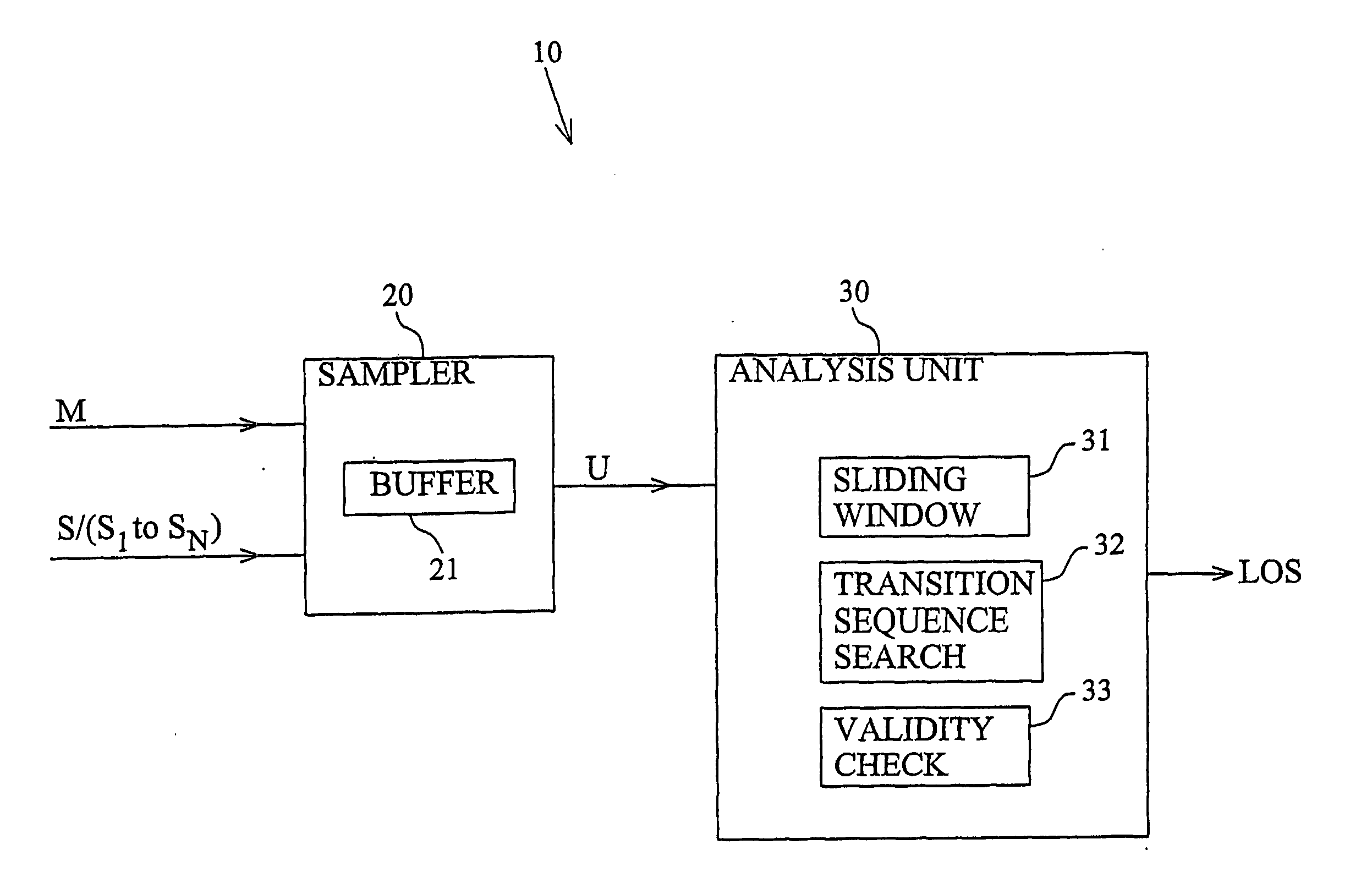
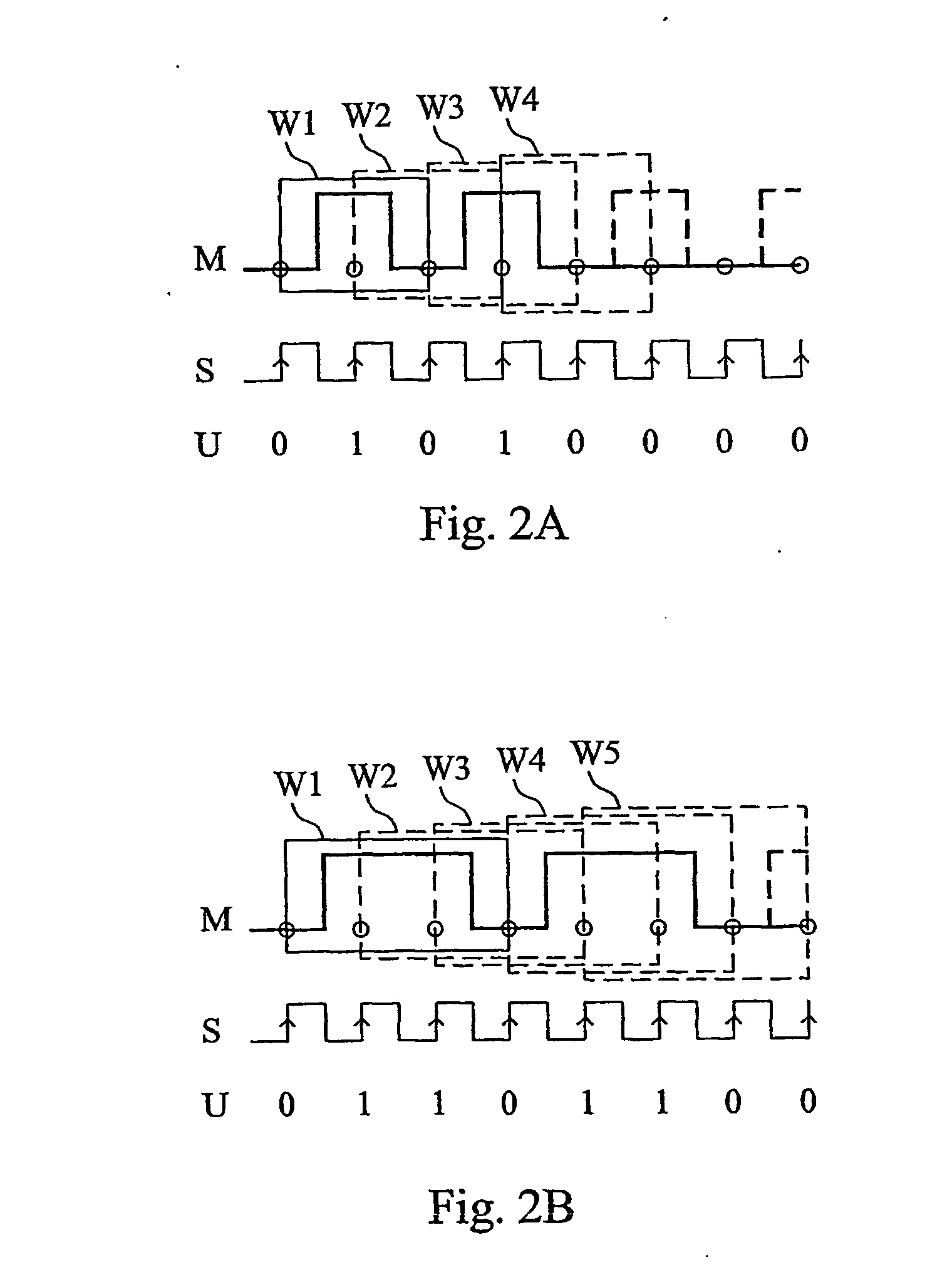
The general idea according to the invention is to monitor a sampled signal by step-wise sliding a window of a predetermined number M of samples over the sampled signal, and determining whether the samples currently in the window include a valid transition sequence. In general, the existence of a valid signal is confirmed as long as a valid transition sequence is present in at least one of a predetermined number of consecutive windows. If the validity can not be confirmed, there is generally a signal failure, for example in the form of a stick low or stuck high fault.

As the name indicates, a transition sequence is a sequence of at least two transitions. Accordingly, a valid transition sequence may for example be a low-to-high “up” transition followed by a high-to-low “down” transition, or any other predefined sequence of transitions. Preferably, for pulse width detection, a ...


PUM


Abstract

The invention is generally directed towards monitoring of a signal (M), such as a clock signal or a data signal, by sampling the signal to obtain a discrete sample representation of the signal and analyzing the sample representation. The idea according to the invention is to slide a sample window (SW) over the sampled signal and determine whether the samples currently within the window include a valid transition sequence. In the general case, the existence of a valide signal is confirmed as long as a valid transition sequence is present in at least one of a predetermined number of consecutive sample windows. In order to reduce the need for oversampling in high-frequency applications, the invention furthermore proposes a multi-phase sampling technique according to which a number of phase-shifted sample clocks (S1 to SN) are generated for the purpose of sampling the signal to be monitored. Higher-frequency oversampling is thus replace by a higher resolution in the time domain.

Description

TECHNICAL FIELD OF THE INVENTION The present invention generally relates to signal supervision, and more particularly to a method and device for signal monitoring. BACKGROUND OF THE INVENTION Supervision and monitoring of signals, such as clock signals and data signals, is of vital importance and signal monitors of various types can be found in many digital electronic systems such as telecommunication systems and other digital communication systems. For example, interfaces and clock paths for a synchronous digital system must continuously be supervised in order to maintain high reliability. Basically, a signal monitor is an arrangement for monitoring the behavior and / or status of a signal. As long as the signal behaves as normal, the signal monitor confirms the existence of a valid signal. On the other hand, if the signal behavior deviates from normal, an alarm is normally raised so that appropriate actions can be taken. The performance evaluation of a signal monitor is normally...

Claims


Application Information

Patent Timeline
Patent Type & Authority Applications(United States)
IPC IPC(8): H03K5/19
CPCH03K5/19
Inventor FREDRIKSSON, JESPER
Owner TELEFON AB LM ERICSSON (PUBL)
Why Eureka
Try Eureka