Air supply apparatus for a fuel cell
a fuel cell and air supply technology, applied in the direction of fuel cells, electrical devices, electrochemical generators, etc., can solve the problems of increasing the size and weight of the fuel cell unit on which the fans are mounted, the pressure (flow rate) of the sucked air is not uniform, and the electric consumption increases. , to achieve the effect of increasing the size and weigh
- Summary
- Abstract
- Description
- Claims
- Application Information
AI Technical Summary
Benefits of technology
Problems solved by technology
Method used
Image
Examples
first embodiment
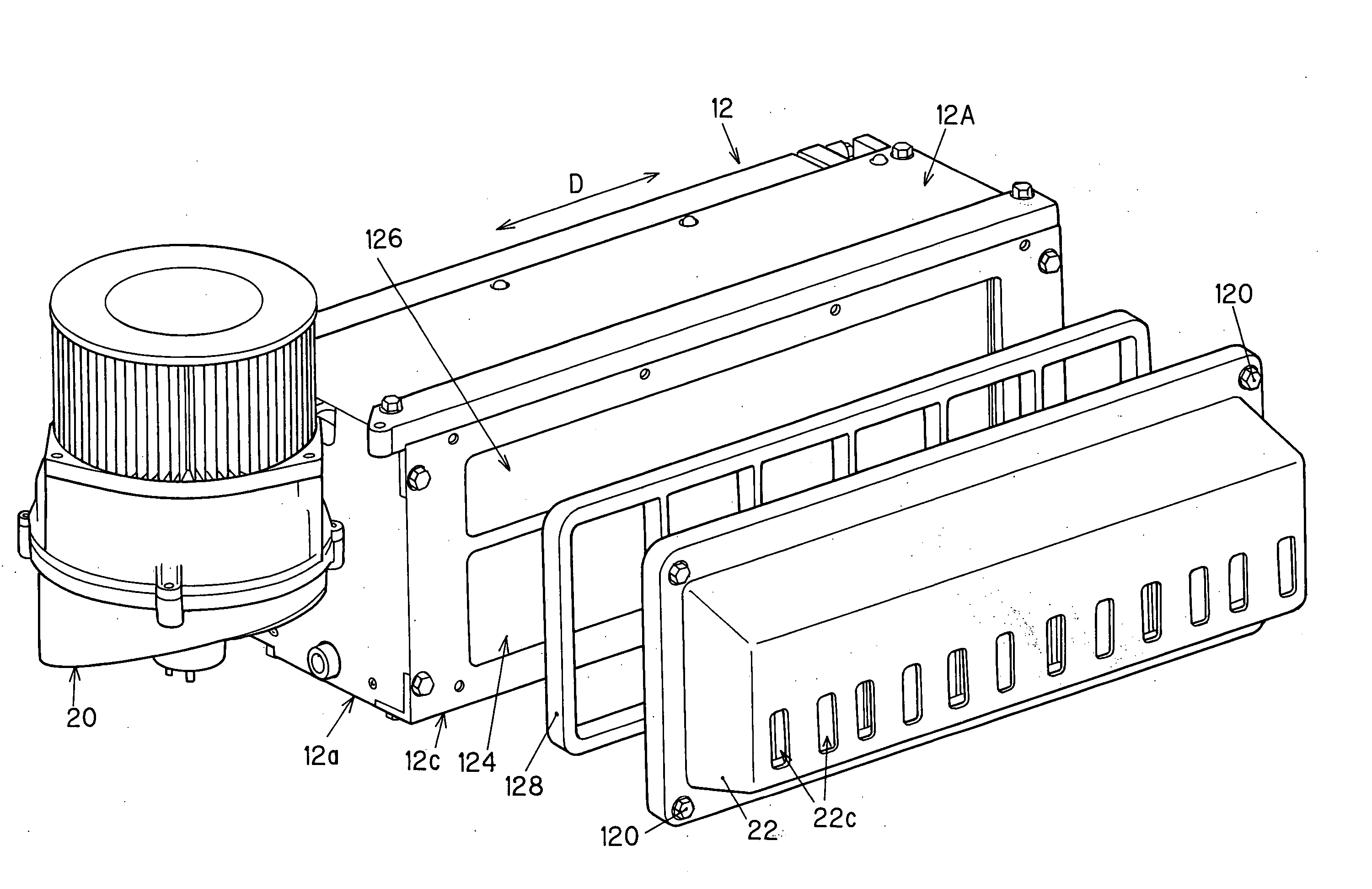
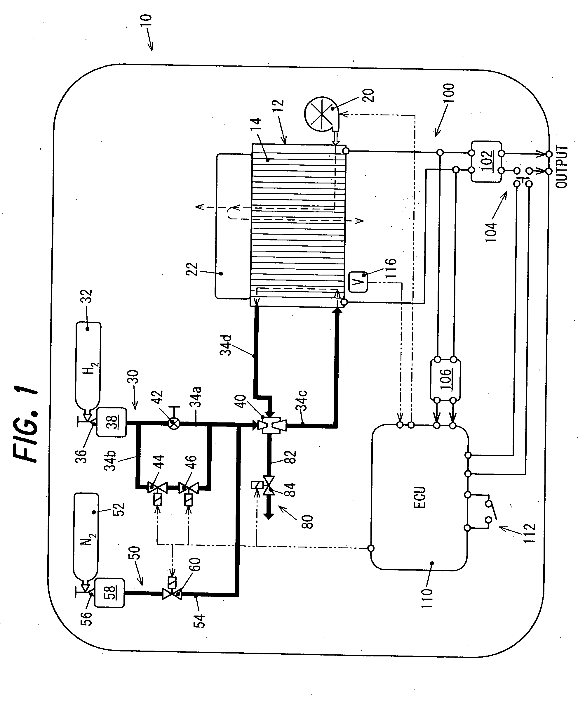
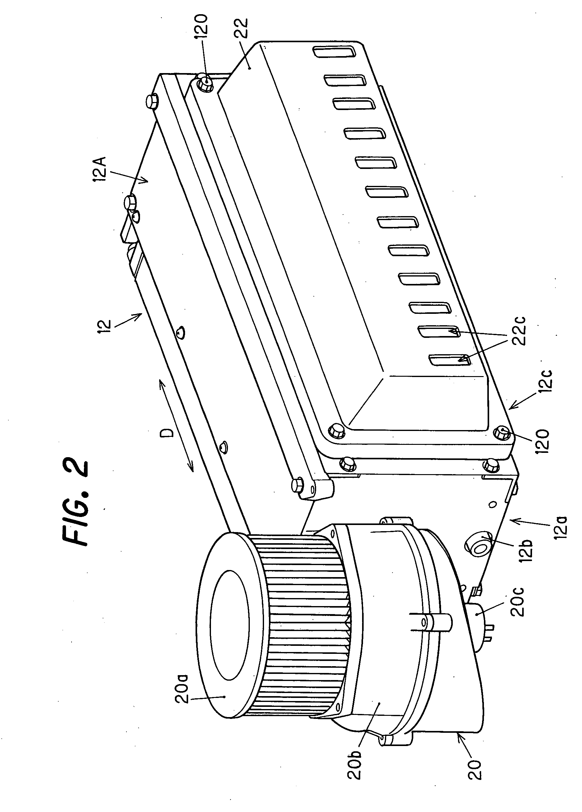
[0027]FIG. 1 is a schematic view showing an air supply apparatus for a fuel cell according to this invention as part of a fuel cell unit.
[0028] In FIG. 1, the symbol 10 indicates a power generating unit including the air supply apparatus for a fuel cell according to the first embodiment. The power generating unit 10 is packaged into a portable size with a fuel cell 12, pipes, and other such elements necessary for power generation.
[0029] The fuel cell (specifically, a stacked member, or cell stack) 12 is formed by stacking a plurality of unit cells (cells) 14. Specifically, 70 cells can be stacked in this manner. The fuel cell generates a rated output of 1.05 kW. The unit cells 14 are conventionally known solid polymer fuel cells including an electrolyte membrane (solid polymer membrane), an air electrode (cathode electrode) and fuel electrode (anode electrode) on both sides of the membrane, and a separator disposed on the outer sides of both electrodes. A detailed description there...
second embodiment
[0068] Next, the air supply apparatus for a fuel cell according to this invention will be described.
[0069]FIG. 6 is a schematic view showing the air supply apparatus for a fuel cell according to the second embodiment of this invention as part of a fuel cell unit. The difference between this embodiment and the first embodiment is that an air blower 220 for feeding cooling air and reaction air to the fuel cell 12 is connected to the fuel cell 12 via a manifold 222, and the air sucked in by the air blower 220 is fed to the unit cells 14 as cooling air or reaction air via the manifold 222. Also, the cooling air and reaction air passing through the unit cells 14 is expelled out of the fuel cell 12.
[0070]FIG. 7 is a perspective view of the fuel cell 12, and of the air blower 220 and manifold 222 connected thereto.
[0071] The fuel cell 12 is provided with a case 212A, and the unit cells 14 are disposed in a stacked arrangement inside the case 212A, as shown in FIG. 7. The side surface 212...
third embodiment
[0085] Next, the air supply apparatus for a fuel cell according to this invention will be described.
[0086]FIG. 9 is a perspective view showing the air supply apparatus for a fuel cell according to the third embodiment. The main difference with the second embodiment is that in the present embodiment, the configuration is such that a sponge plate is provided as a flow-uniforming device instead of a punching plate.
[0087] In FIG. 9, the symbol 322h indicates a plate of sponge made of urethane (i.e., a sponge configured to be a plate). The sponge plate 322h is disposed downstream of the current plates 222f (between the expanding section 222e and the air discharge vent 222d) via a metallic base plate 322i provided with a plurality of large holes.
[0088] Specifically, in the third embodiment, the air sucked in by the air blower 220 is made more uniform by the current plates 222f to have a substantially uniform current speed, and is then made more uniform and endowed with a uniform current...
PUM
 Abstract
Description
Claims
Application Information
 - R&D
- Intellectual Property
- Life Sciences
- Materials
- Tech Scout
- Unparalleled Data Quality
- Higher Quality Content
- 60% Fewer Hallucinations
Browse by: Latest US Patents, China's latest patents, Technical Efficacy Thesaurus, Application Domain, Technology Topic, Popular Technical Reports.
© 2025 PatSnap. All rights reserved.Legal|Privacy policy|Modern Slavery Act Transparency Statement|Sitemap|About US| Contact US: help@patsnap.com


