Electrical connector

a technology of electrical connectors and connectors, which is applied in the direction of coupling device connections, coupling protective earth/shielding arrangements, electric discharge lamps, etc., can solve the problems of easy short circuits between the tail portions or the wires, laborious soldering of the tail portions of the contacts with the wires of the cable, and the notebook miniaturization trend of the dvi plug and receptacle connectors. to achieve the effect of simplifying soldering

Inactive Publication Date: 2005-01-20
HON HAI PRECISION IND CO LTD
View PDF6 Cites 33 Cited by
  • Summary
  • Abstract
  • Description
  • Claims
  • Application Information

AI Technical Summary

Benefits of technology

[0007] An object of the present invention is to provide an electrical connector which can simplify soldering between tail portions of contacts thereof and wires of a cable.
[0008] Another object of the present invention is to provide an electrical connector which can prevent short circuits between tail portions of contacts thereof.

Problems solved by technology

Due to an arrangement of the contacts, the conventional DVI plug and receptacle connectors are unadapted for the miniaturization trend of the notebook.
It is labourious to solder the tail portions of the contacts with wires of a cable.
Furthermore, after the tail portions have been soldered with the wires of the cable, short circuits between the tail portions or the wires occur easily.

Method used


Image

  • Electrical connector
  • Electrical connector
  • Electrical connector

Examples


Embodiment Construction

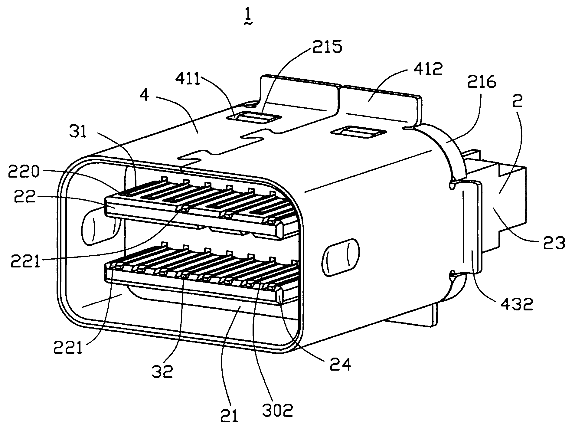
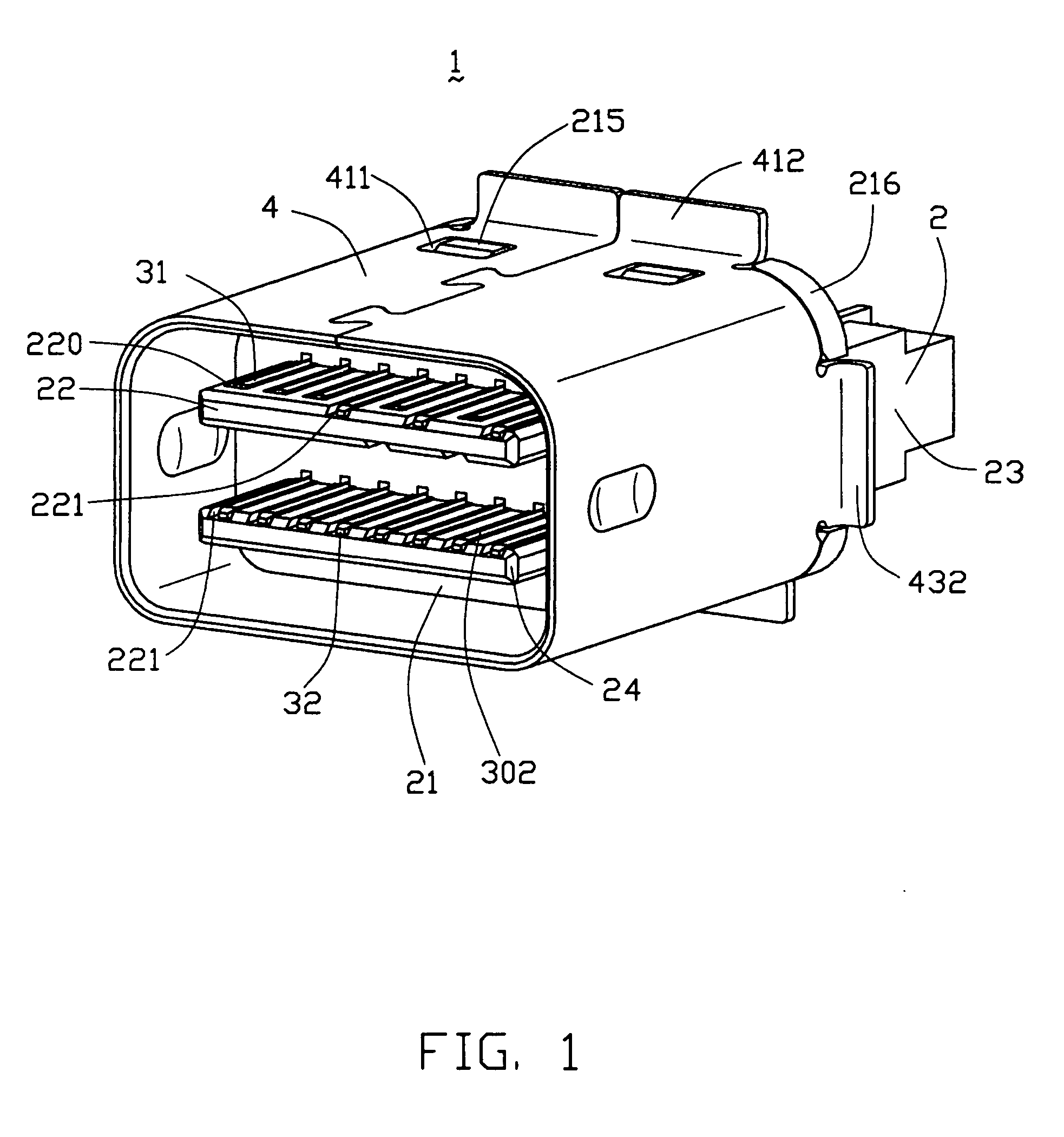
[0019] Referring to FIGS. 1, 3 and 6, an electrical connector 1 in accordance with the present invention comprises an insulative housing 2, a plurality of contacts 3 and a shell 4.

[0020] The insulative housing 2 comprises a main body 21, a first and a second tongues 22, 24 extending forwardly from the main body 21, and a mounting portion 23 extending rearwardly from the main body 21. The main body 21 has an upper face 211, a lower face 212 opposite to the upper face 211, and two opposite side faces 213 connecting the upper face 211 with the lower face 212. Each of the upper and the lower faces 211, 212 is formed with a pair of projections 215 thereon and a pair of stoppers 216 on rear ends thereof and adjacent to the side faces 213. The first tongue 22 is parallel to and vertically aligned with the second tongue 24. The first tongue 22 defines a plurality of signal passageways 220 and a plurality of ground passageways 221 on an upper surface thereof, a plurality of signal passagewa...


PUM


Abstract

An electrical connector (1) includes a housing (2), a number of contacts (3) received in the housing, and a shell (4) retained to the housing. The housing includes a main body (21), a first and a second tongues (22, 24) extending forwardly from the main body, and a mounting portion (23) extending rearwardly form the main body. The first and the second tongues define a number of passageways extending rearwardly throughout the main body. The mounting portion has a first and a second faces (2311,2312) on a first side (231), a third and a fourth faces (2321, 2322) on a second side (232), and a number of channels on the first, the second, the third and the fourth faces and communicating with the passageways. The second and the fourth faces are behind and offset from the first face and the third faces respectively.

Description

BACKGROUND OF THE INVENTION [0001] 1. Field of the Invention [0002] The present invention generally relates to an electrical connector, and particularly to an electrical connector adapted for the miniaturization trend of electronic field. [0003] 2. Description of Related Art [0004] A micro coaxial cable assembly (MCCA) is usually used to connect a liquid crystal display (LCD) with a mother board of a notebook computer for providing video signal transmission therebetween. In some applications, the video signal needs to be transmitted from the mother board to a peripheral display device for obtaining a good visual effect. The video signal transmission between the mother board and the peripheral display device is generally carried out by a cable connector assembly having two DVI plug connectors connected by a cable and mating with two corresponding DVI receptacle connectors mounted on the mother board and the peripheral display device, respectively. Referring to FIG. 8, a conventional ...

Claims


Application Information

Patent Timeline
Patent Type & Authority Applications(United States)
IPC IPC(8): H01R11/01H01R24/00
CPCH01R4/023H01R13/6585H01R24/60H01R2107/00
Inventor JI, RENHUALIN, YISHENG
Owner HON HAI PRECISION IND CO LTD
Why Eureka
Try Eureka